
| Optimizing Meter Inputs for Phase Angle & Power Factor Measurement |
|---|
|
Phase angle and power factor measurement with the Laureate™ Phase Angle & Power Factor Meter require that two signals of identical periods be applied to Channels A and B. For best accuracy, both signals should have the same amplitude, the signal amplitude should be larger than 1V, and the trigger level should be minimized by selecting the ±12 mV jumper position. The meter times zero crossings to 0.1 µs resolution over a user-selectable gate time from 10 ms to 199.99 s. By selecting the minimum gate time of 10 ms, the meter update rate will be approximately 20/s for 50/60 Hz AC line frequency. Improved accuracy will be obtained by making the gate time long enough so that multiple cycles are averaged. Both signals applied to the meter should be mutually isolated by transformer coupling, so that they can then share the same ground in the meter. The current signal is typically obtained from a current transformer (CT). This should ideally be a CT with a voltage output or a current output in the mA range, which can then be converted to a voltage higher than 1V across an external dropping resistor without excessive heat generation. |
| Using Laureate Meters and Counters to Synchronize Motor Generators |
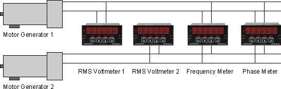
Synchronization of two motor generators requires that the two frequencies be identical, that the lines be in phase, and that the line voltages be close to each other. In this illustration, a single Laureate dual channel counter measures both frequencies to six-figure accuracy in a few line cycles. Another Laureate dual channel counter measures phase angle to 0.1° resolution. Two Laureate AC RMS Voltmeters, which offer ranges of 200.00 V and 600.0 V, are used to display the two RMS voltages to 0.1% accuracy. |
