|

|
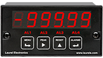
| 1/8 DIN Digital Panel Meters |
DIN Rail Transmitters |
Free Downloadable Windows-based Instrument Setup (IS) software for Series 2 Laureates used with Digital Panel Meters, Scale Meters, Counters, Timers, Remote Displays, and Transmitters, are an easy method to set up Laureate 1/8 DIN digital panel meters, counters, timers, remote displays, and DIN-rail transmitters, as explained in the Instrument Setup Software Manual. Laureate 1/8 DIN instruments can also be set up from the front panel, as explained in their respective Owners Manuals. Instrument Setup software is of benefit whether or not the PC is connected to the instrument.
- When the PC is connected to the instrument, Instrument Setup software can get the setup file from the instrument or open a default setup file or previously saved setup file from disk View Setup, then provides graphical user interface (GUI) screens which pull-down menus applicable to input, display, scaling, filtering, alarms, communications, analog output, and front panel lockouts. Fields that are not applicable to the instrument as configured are either left out or grayed out. Clicking on any item will bring up a detailed Help screen for that item. Once edited, the setup file can be downloaded or put into the instrument and be saved to disk. The same setup file can then be downloaded into multiple instruments.
- When the PC is not connected to the instrument, the above GUI screens can be used to set up a virtual instrument. The setup file can then be saved to disk. Switching toView Menu then brings up a screen with the required front panel programming steps. This view can be printed out for use at the instrument site and to serve as a hard copy record.
Installation
Set User Account Control (UAC) of MS Windows to "Never notify me" so that Instrument Setup Software can create directories. The UAC change screen can be reached as follows:
- Under Windows 7, click on the Windows Start button in the lower left of the desktop and enter "UAC" in the search field.
- Under Windows 8, navigate to Control Panel, then to the "User Accounts and Family Safety" section, and click on "Change User Account Control Settings."
- Under Windows 10, click on the Windows Start button in the lower left of the desktop, then on "Settings", and enter "UAC" in the search field.
- Reboot your computer for the changed UAC setting to take effect.
RJ11-to-DB9 cable with rear view of DB9 connector to PC
Laureate 1/8 DIN Laureate instruments must be equipped with a serial communications board and be connected to the computer via a serial communications cable. The connection can be via RS232, RS485, USB or Ethernet. Following setup, the serial communications board may be removed from the instrument if desired. The wiring of the RS232 cable is illustrated above with end views of the two connectors.
Laureate LT Series transmitters come standard with a 3-wire serial interface, which can be jumpered for RS232 or RS485.
Laureate LTE Series transmitters come standard with an Ethernet interface.
Meter Setup Screens
Click on any of the reduced screens below for a full-size screen view, then click on the Back button of your browser to return to this page. The screens examples below are for a fully-loaded Series 2 Digital Panel Meter (DPM), which is connected to the PC via RS232. If the meter is a Series 1 meter (pre-2007), this is sensed by the software, and somewhat different screens are brought up. Please see Series 1 setup screens.
Welcome Screen
From the computer desktop, click on
Start > Programs > IS2 > IS2. Or click on the
IS icon on your desktop. This splash screen will be displayed for three seconds. The software revision number is in the lower right.

Communications Selection Screen
Specify your desired communication protocol and the serial communications bus type, which should match the jumper setup of the instrument. Select
None if the PC is not connected to the instrument.
Establish Communications Screen
If you selected RS-232, you will be asked to specify the PC Com Port and Baud Rate, which should match the jumper setup of the instrument. Click on
Establish. With the right settings, the
Communications Established field will light up in green, and the
Meter Type will be recognized. If so, click on
Main Menu.
Main Menu Screen
Click on
File > Default Setup to retrieve the default setup file from disk for your type of meter. Click on
File > Open Setupto retrieve a previously saved setup file from disk or on
File > Save Setup to save your edited setup file to disk. Click on
DPM > Get Setup to retrieve the setup file from your meter or on
DPM > Put Setup to download your edited setup file into the meter.
DPM Input + Display Setup Screen
From the Main Menu, click on
View > Setup, then on the
Input+Display tab. You can now specify the meter hardware, signal type, display mode, and functions of control inputs A and B. Clicking on any item brings up a pull-down menu with the available choices.
DPM Scaling Setup Screen
Click on the
Scaling tab, which provides three scaling methods to relate the signal to the displayed reading: 1) Scale and Offset method, 2) Coordinates of two points method, and 3) Reading Coordinates of Two Points method. The last method uses actual high and low signals, and the computer will prompt you.
DPM Filter Setup Screen
Click on the
Filter tab, which allows you to specify the digital filter time constant (if any), the adaptive filter threshold, and whether Peak / Valley values are filtered or unfiltered. As for all setup screens, clicking on the F1 key while an item is highlighted brings up a Help screen for that item, as illustrated.
DPM Relay Alarms Setup Screen
Click on the
Relay Alarms tab, which allows you to set up Alarms 1 and 2 for the optional dual relay output board. Clicking on any of the four numeric fields changes these to green and brings up a special field to enter the desired numeric value, which is tied to the displayed reading.
DPM Communications Setup Screen
Click on the
Communications tab so set up serial communications. In particular, you can special the Serial Protocol and the meter address if multiple meters are to be addressed on the same serial data line.
DPM Analog Output Setup Screen
Click on the
Analog Out tab so set up the optional analog output board. Three output ranges are selectable, the endpoints of which can be tied to user-specified High and Low readings.
DPM Lockouts Setup Screen
Click on the
Lockouts tab to check off menu items which will no longer be accessible from the front panel of the meter. This will simplify meter operation and prevent unintended setup changes.
Meter Setup Utilities
DPM Front Panel Setup Screen
As an aid to programming the meter from the front panel when a serial connection is not available, you can return to the Main Menu and click on
View > Menu. The required sequence of front panel screens will then be displayed. Click on any step in the sequence for the meaning of each digit, as illustrated for the
FILtEr step. For a hardcopy, simply press on
Print.
DPM Jumper Setup Screen
Specify your desired communication protocol and the serial communications bus type, which should match the jumper setup of the instrument. Select
None if the PC is not connected to the instrument.
DPM Jumper Setup Screens
Click on any of the displayed plug-in boards, and you will be presented with the jumper positions and electrical connections for your selected board. This minimizes the need to refer to the printed manual.
DPM Commands Screen
This page allows you set up external input, serial communications, an analog output proportional to the display (optional), and lockouts for Laureate digital counters. The grayed out area at the top right of the screen applies to
Laureate remote displays.
Graphical Output Screens (not available with Ethernet)
From the Main Menu, click on Readings if your PC is connected to the meter. A pull-down menu then offers three choices: List, Plot and Graph.
- List presents the latest readings in a 20-row by 10-column table. Press Pause at any time to freeze the display. This is one method to capture peak readings.
- Plot generates a plot of readings vs. time in seconds. It effectively turns the DPM-PC combination into a printing digital oscilloscope.
- Graph generates a histogram where the horizontal axis is the reading and the vertical axis is the number of occurrences of readings. The display continually resizes itself as the number of readings increases.
DPM Calibration Screens
Click on the
Scaling tab, which provides three scalClick on the
Scaling tab, which provides three scaling methods to relate the signal to the displayed reading: 1) Scale and Offset method, 2) Coordinates of two points method, and 3) Reading Coordinates of Two Points method. The last method uses actual high and low signals, and the computer will prompt you.
Frequency Meter Calibration Screen
Calibration of the quartz crystal of the Laureate frequency meter requires the input of a known frequency from a calibrator. Apply the frequency, then enter the frequency in Hertz. Calibration will be automatic, with storage of the calibration factor stored in non-volatile memory.