
PC-based data logging with Laurel meters and transmitters.
A flexible data logging system is created when a PC running Laurel's XLog2 datalogging software is connected to Laureate meters (DPMs, counters or timers) and transmitters. The logged data can be captured in the form of text files or MS Excel written directly to disk. It can also be displayed by the PC in the form of up to 64 simulated panel meters in up to 4 groups (or screens) of up to 16 meters each. The on-screen position and appearance of individual meters is user selectable to achieve meaningful groupings. User settable parameters include the logging time interval in seconds and header data with or without time and date. Data files can be password protected. Works with Modbus RTU, Modbus ASCII, Modbus TCP, and Custom ASCII protocols.
The data connection between the PC and the instruments can be via Ethernet, RS485, USB or RS232.
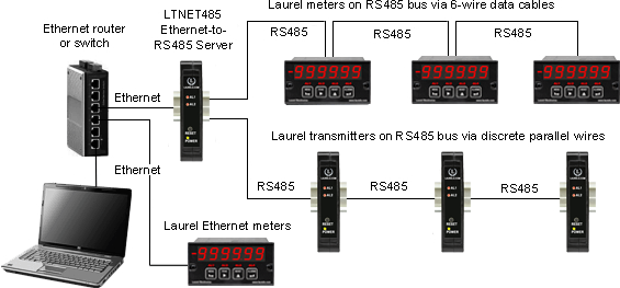
- Ethernet connection: The instruments can be any mix of meters with an LNET Ethernet interface board, meters with an LNET485 Ethernet-to-RS485 interface board, and DIN-rail mounted LTE series transmitters. The Ethernet-to-RS45 interface board supports its host meter plus another 30 RS485 enabled instruments on an RS485 bus. These can a mix of Laureate meters with an RS485 interface board and Laureate LT series transmitters, which come standard with an RS485 port. Automatic discovery of all instruments on the LAN and on each RS485 bus is achieved by Laurel's XLog2 Datalogging Software. With an Ethernet connection, remote instruments can be logged over the Internet.
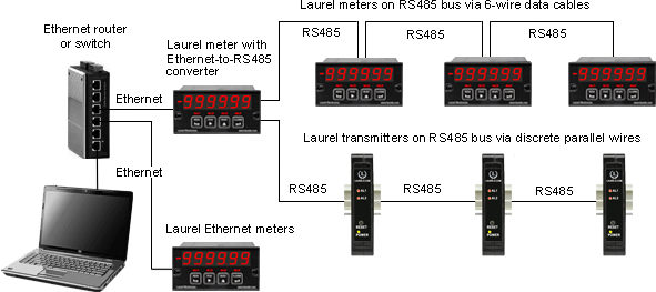
Data logging over an Ethernet and RS485 network
- RS485 connection: Up to 31 actual instruments can be addressed on the same data line, and up to 64 instruments can be displayed, including 33 virtual instruments. The latter can show calculated parameters which combine data from multiple actual instruments. For example, a virtual meter can display watts, obtained by multiplying the current reading from one meter by the voltage reading from another meter. Available operands are multiply, divide, add and subtract. Parentheses allow complex expressions. The 31 actual instruments can be any mix of Laureate meters with an RS485 interface board plus Laureate LT series transmitters, which come standard with an RS485 port. Automatic discovery of all instruments on the RS485 bus is achieved by Laurel's XLog Datalogging Software.
- USB connection: The USB port of a PC can be connected to a single meter with a USB interface board. The USB standard specifies a maximum cable length of 5 meters. Up to 31 actual instruments plus 33 virtual instruments can be interfaced to a PC with a single USB port if the USB signal is converted to an RS485 signal. This can be achieved by our CBL06 adapter cable or by a USB-to-RS485 converter board in the first meter. The RS485 instruments can be a mix of Laureate meters with an RS485 interface board and Laureate LT series transmitters, which come standard with an RS232/485 port. Automatic discovery of all instruments on the RS485 bus is achieved by Laurel's XLog Datalogging Software.
- RS232 connection: RS232 is designed for a point-to-point connection and is suitable for datalogging with a single instrument connected to a PC COM port. The instrument can be a Laureate meter with an RS232 interface board or a Laureate LT series transmitter, which comes standard with an RS232/485 port.
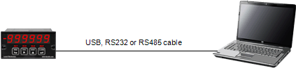
Data logging with a single Laurel instrument
(The instrument and PC must support the chosen interface)
(The instrument and PC must support the chosen interface)
Datalogging Software Installation
Set User Account Control (UAC) to "Never notify" so that Datalogging Software can create directories. The UAC change screen can be reached as follows:
- Under Windows 7, click on the Windows Start button in the lower left of the desktop and enter "UAC" in the search field.
- Under Windows 8, navigate to Control Panel, then to the "User Accounts and Family Safety" section, and click on "Change User Account Control Settings."
- Under Windows 10, click on the Windows Start button in the lower left of the desktop, then on "Settings", and enter "UAC" in the search field.
- Reboot your computer for the changed UAC setting to take effect.
Laureate XLog2 Datalogging Software available from this website. See XLog2 sample screens and our Datalogging Manual.
Use of PC without Datalogging Software
Datalogging Software is not required for use of Laureate products with a PC. Most people use the Modbus protocol or the simpler Laurel ASCII protocol to communicate directly and read and write memory addresses. Please see Laurel's Modbus Manual for Analog Input Meters or Transmitters, Laurel's Modbus Manual for Pulse Input Counters or Transmitters, and Laurel's ASCII Serial Communications Manual. Reading and writing memory addresses with custom software provides speed and flexibility.
Laureate™ XLog2 Datalogging Software Screens
Data logging with Ethernet and RS485 enabled Laurel instruments
This web page presents sample screens of Laurel's XLog2 data logging software, which has been available since August 2012. Click on any of the reduced screens below for a full-size screen view.
 |
Open the Demo Setup File To get started from the computer desktop, click on Start > Programs > Logging Software > Logging Software. Then click onSetup File > Open > DEMO.SF1 > Open to load the supplied Demo setup file and open the Menu screen. |
 |
Set Up Default Meter Appearance Click on Meter Setup > Default Meter Face. This will open the Common Setup screen, which allows you to select the number of meters per group (up to 4 groups), default meter colors, and default font size for meter captions. |
 |
Set Up Individual Meters Return to the Main screen and click on Meter Setup > Create Meters. The resulting Individual Meter Setup screen will allow you to specify the I.D., Caption, Meter Type, Serial Address, and Item Number associated with each meter. An arithmetic formula can be entered in the right column for virtual meters. |
 |
Set Up Individual Meter Appearance Return to the Main screen and click on Meter Setup > Edit Meter Face. In the resulting Edit Meters screen, right-click on any meter to override that meter's default colors and font sizes to make that meter stand out from the rest. |
 |
Specify the Data to be Logged Return to the Main screen and click on Log Setup. Specify the name of the setup file, the type of data to be logged, and the logging interval in seconds. Then click on Next. |
 |
Select Meters and Establish Communications In the resulting Establish screen, you can Log Enable specific meters, whose record position will then be shown. Click onEstablish Initial Communications to begin logging. |
 |
Datalogging Display Screens The display is updated for each meter in real time, including any alarm indications, while data is also written to disk. Similar screens are available for Groups 2-4. |
 |
Navigation to Datalogging Help Screens Pressing on Help on the top menu bar brings a pull-down menus for navigation to comprehensive help screens. |
 |
Sample Help Screens The first help screen in the sequence provides an overview of the Logging software. In combination, the help screens serve role of a printed manual. |
