New Front Panel USB-C Port Coming Soon!
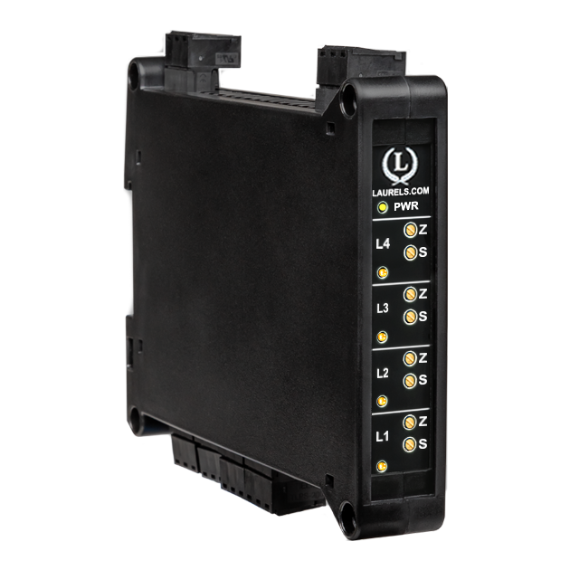
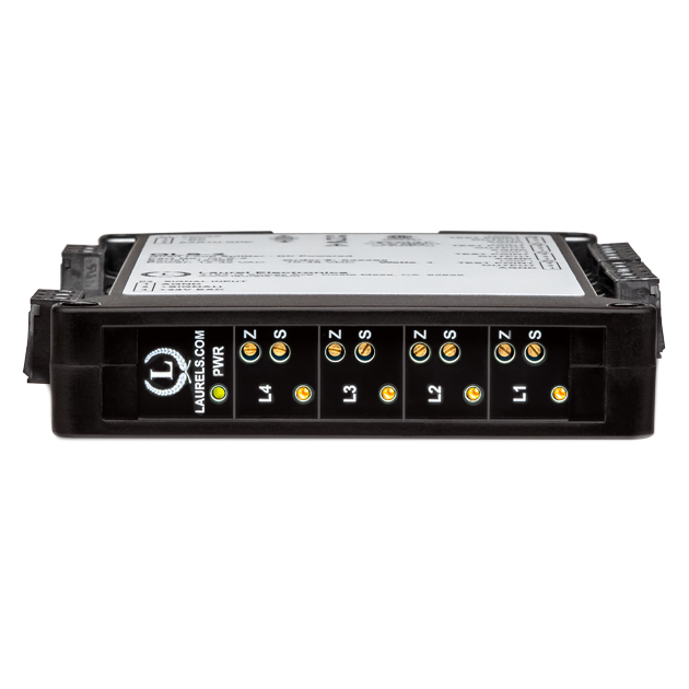
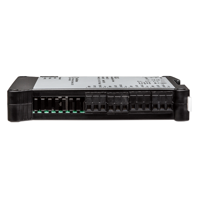
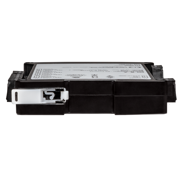
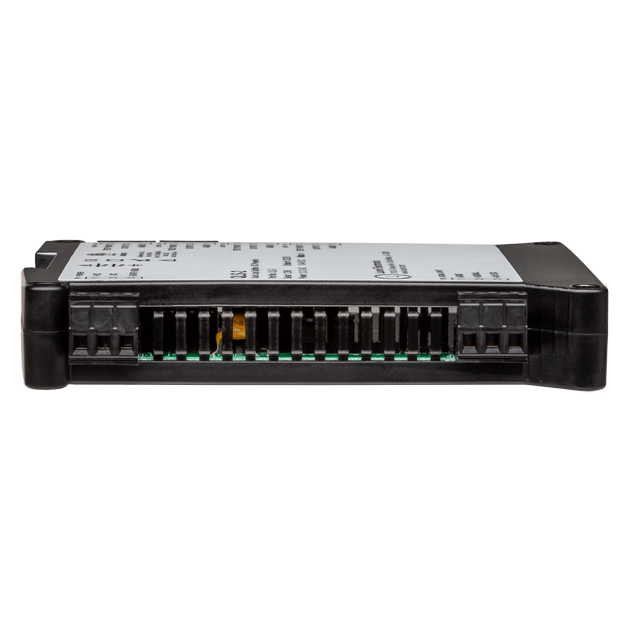
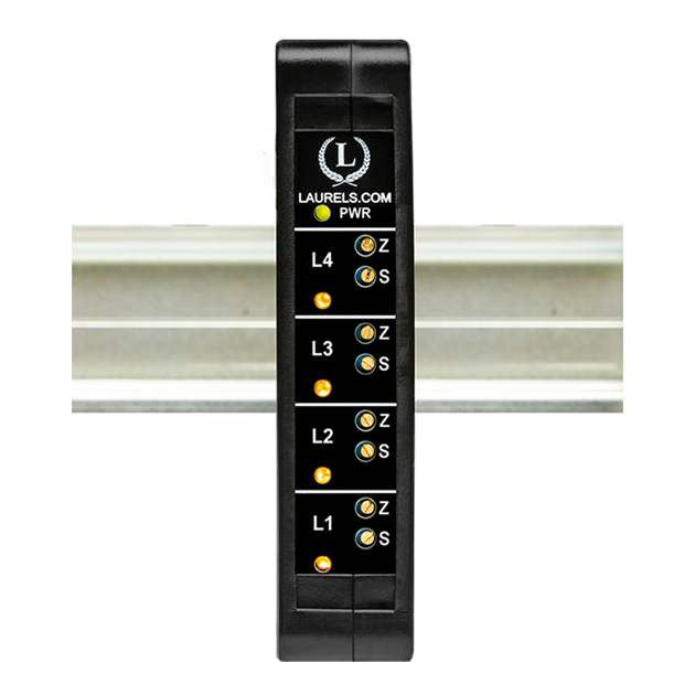
The DIN Rail Transmitter for Quad Current Loop Splitter / Retransmitter accepts 4-20 mA, 1-5V, 0-5V, or 0-10V inputs and drives four independent 4-20 mA outputs with ±10V common mode isolation. It supports shared or ±10V differing grounds, with each loop featuring ±10% zero/span adjustments, a 200 mV = 20 mA test point, and an LED indicator. Powered by 85-264 Vac/90-300 Vdc, it powers 2- or 3-wire transmitters at 24 Vdc up to 30 mA. Housed in a 22.5 mm case for 35 mm DIN rail, it weighs 159 g and operates from -40°C to 70°C, with CE, RoHS3, and ETL certifications. The LT Quad Current Loop Splitter solves series loop issues by providing four adjustable outputs from one input, ensuring unaffected loops if one fails. It includes LED diagnostics and test points, enhancing reliability and ease of use.
The QLS-1 Quad Current Loop Splitter / Retransmitter is factory-calibrated. For optimal accuracy, factory recalibration is recommended annually. All Laurel Electronics instruments undergo factory calibration using the industry-leading Fluke calibrators, which are recalibrated yearly and certified traceable to national standards, ensuring the highest level of precision and reliability.

| Common Practice: | A single 4-20 mA loop from a sensor is connector to a panel meter, a control valve, a recorder and a PLC in series. If the loop opens, all devices in the loop fail. |
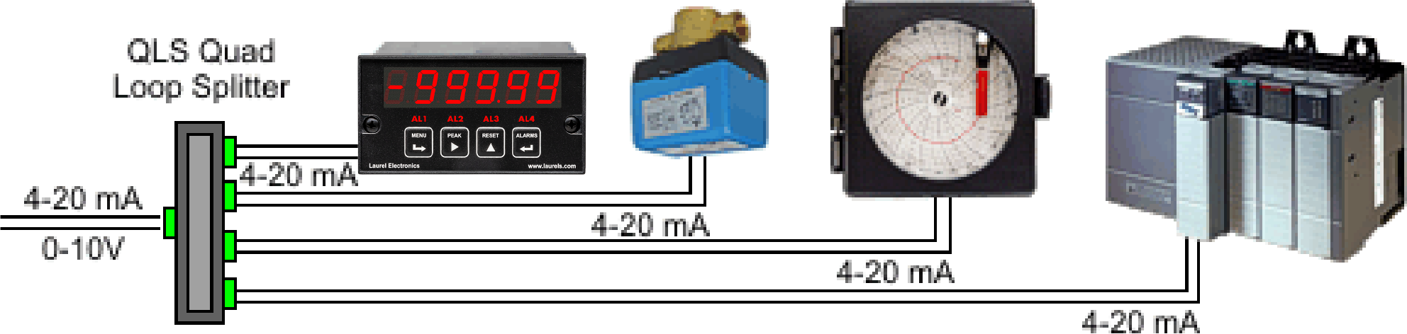
| Improved Practice: | Four independent 4-20 mA loops with ±10V common mode isolation. If any of the output loops opens, only a single device is affected. The output loops can share a common ground. |
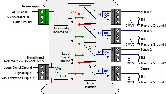
Galvanic & Active Isolation: A single input current loop is split into four independent output loops I1, I2, I3 and I4 by four current generators. The input and output signals are galvanically isolated from power and earth grounds by up to 264 Vac. Active circuitry allows a common mode voltage up to ±10V between Local Signal Ground (on pins 1) and the Remote Grounds. Each common mode voltages, labeled CMV1 to CMV4 in the diagram, reflects the actual voltage difference between Local Signal Ground and the Remote Ground. Such differences can be caused by current flows in the factory.
Floating loads: Any output load R that is floating (not connected to Earth Ground or a Local Ground) can be connected between current output (Pin 1) and current return (Pin 2). Current return is internally tied to Signal Ground, which can be floating or be connected to Earth Ground.
Grounded loads: Any output load R can be connected to a Local Ground instead of current return. The Remote Grounds can each be different, but can only differ from Signal Ground by a safe common mode voltage CMV. Signal Ground should be tied to Earth Ground to minimize noise pickup.
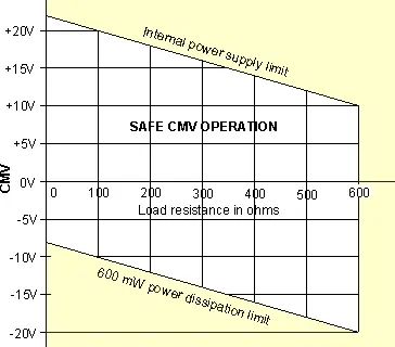
Input-output isolation: If a load R is grounded to a Local Ground, the available common mode voltage CMV is limited on the positive side by the unit's internal power supply and on the negative side by the 600 mW power dissipation limit of an output transistor. The above diagram shows allowable CMV as a function of output load resistance R. For example, with a 250Ω load, CMV can range from -13V to +17V. With a 500Ω load, CMV can range from -18V to +12V. The unit will not work correctly if CMV limits are exceeded or the load resistance is greater than 600Ω.
| Signal Input & Excitation | ||||
|---|---|---|---|---|
| Signal Type | 4-20 mA, 1-5V, 0-5V, 0-10V (jumper selectable) | |||
| Input Resistance | 50Ω for 4-20 mA, 412kΩ for 1-5V, 464kΩ for 0-5V, 935kΩ for 0-10V | |||
| Transducer Excitation | 24 Vdc output, 30 mA max | |||
| Signal Outputs | ||||
| Number of Outputs | 4 | |||
| Signal Type | 4-20 mA | |||
| Signal Ground | Same signal ground for input and outputs | |||
| Common Mode Voltage | Remote signal grounds can be up to ± 10V from local signal ground | |||
| Zero & Span Adjustments | ± 10% for each output with 25-turn potentiometers | |||
| Isolation Power to Signals | 264 Vac | |||
| Voltage Compliance | 12V (600Ω per loop at 20 mA) | |||
| Load Regulation | ± 0.005% of span from 0Ω to 600Ω | |||
| Accuracy | ± 0.02% max span error at 23°C | |||
| Zero Tempco | ± 0.1 µA/°C typical, ± 0.2 µA/°C max | |||
| Span Tempco | ± 10 ppm/°C (0.16 µA/°C) typical, ± 20 ppm/°C (0.32 µA/°C) max | |||
| AC Rejection | 90 dB from DC to 60 Hz | |||
| Response Speed | 2 ms risetime, 7 ms settling time to 0.1% of final value | |||
| Loop Current Sense | 10Ω ± 0.5% series resistor. Generates 200 mV at 20 mA | |||
| Loop Continuity Indication | Yellow LED lamp per loop, brightness proportional to current. | |||
| Power Input | ||||
| Model QLS-1 | 85-264 Vac or 90-300 Vdc | |||
| Model QLS-2 | 10-48 Vdc or 12-32 Vac | |||
| Power Frequency | DC or 47-63 Hz | |||
| Power Isolation | 250V AC working, 1.0 kV AC for 60 sec, 1.7 kV DC for 2 sec | |||
| Power Consumption | 3.5 W max, all loops delivering 20 mA | |||
| Power On Indication | Green LED lamp | |||
| Environmental | ||||
| Operating Temperature | -40°C to 70°C (-40°F to 158°F) | |||
| Storage Temperature | -40°C to 85°C (-40°F to 185°F) | |||
| Relative Humidity | 95% at 40°C, non-condensing | |||
| Cooling Required | Mount transmitters with ventilation holes at top and bottom. Leave 6 mm (1/4") between transmitters, or force air with a fan. | |||
| Mechanical | ||||
| Enclosure | Rugged black polycarbonate housing material | |||
| Mounting | 35 mm rail per DIN EN 50022 | |||
| Dimensions | 129 x 104 x 22.5 mm case | |||
| Connectors | Detachable screw clamp connectors meet VDE / IEC / UL / CSA standards. RJ45 jack for Ethernet | |||
| Tightening Torque | Screw terminal connectors: 5 lb-in (0.56 Nm) | |||
| Weight | Complete transmitter: 183 g (6.5 oz) | |||
| Replacement Case Screws | ||||
| Size | 6 | |||
| Thread Pitch | 6-19 | |||
| Length | 1/2" | |||
| Head Style | Pan Head | |||
| Drive Style | Phillips | |||
| Head Diameter | 0.256-0.270 | |||
| Head Height | 0.087-0.097 | |||
| Full/Partial Thread | Full | |||
| Drive Size | 2 | |||
| Material | Steel | |||
| Finished | Black Oxide | |||
| General | ||||
| Warranty | 3 years parts & labor | |||
| Recalibration: All ranges are calibrated at the factory. Recalibration is recommended every 12 months. | ||||
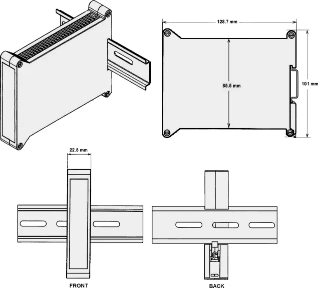
Dimensioned CAD assembly drawings in EPRT, STEP, x_t, .dwg, pdf file formats: Laureate-transmitter-case.zip (zipping prevents browser from opening CAD files as text files).
The Laureate QLS-1 is a DIN rail-mounted current loop splitter for standard industrial AC and high-voltage DC powered panels. It accepts a single 4-20 mA, 1-5V, 0-5V, or 0-10V input signal and drives four fully independent, isolated 4-20 mA output loops — powered by 85-264 Vac or 90-300 Vdc.
The QLS-1 is the right choice when panel power is 120 Vac, 240 Vac, or a high-voltage DC bus — the standard in most industrial plants, utility substations, power generation facilities, and heavy manufacturing environments. It operates across the full international AC voltage range without adjustment, making it equally suited for North American 120 Vac panels and European 240 Vac installations.
Like all QLS models, it eliminates the reliability and grounding problems of series current loop wiring by driving each of its four output loops from an independent current generator. A fault, open circuit, or device failure on one output loop has no effect on the other three.
Most large industrial facilities run control panels on 120 Vac or 240 Vac. Adding a separate 24 Vdc power supply just to run a current loop splitter adds cost, panel space, and another potential point of failure. The QLS-1 eliminates that extra component by running directly from the panel's existing AC power — the same circuit feeding the PLCs, drives, and instrumentation already installed.
Its wide 85-264 Vac input range covers the full global AC supply range in a single unit, simplifying procurement for multinational manufacturers and OEMs building equipment for international markets. The 90-300 Vdc input extends compatibility to high-voltage DC bus systems found in power generation and distribution applications.
The QLS-1 accepts 4-20 mA, 1-5V, 0-5V, or 0-10V input via onboard jumper selection. This covers the full range of standard industrial transmitter outputs, from two-wire 4-20 mA sensors to voltage-output signal conditioners, without requiring additional conversion hardware.
Four independent current generator circuits each reproduce the input as a proportional 4-20 mA output. Each loop is galvanically isolated from the power supply, with active common mode compensation allowing remote ground references to differ from local signal ground by up to ±10V. This accommodates the real-world ground potential differences between field devices, junction boxes, and control room panels in large industrial facilities — where long cable runs and high fault currents commonly produce such differences.
Each output loop includes a 25-turn potentiometer for ±10% zero and span adjustment, enabling independent calibration of each connected device. A 10Ω test point resistor generates 200 mV at 20 mA full scale — touchable with a standard multimeter to read loop current without opening the circuit. A yellow LED per loop glows proportionally to loop current, providing an immediate visual indication of loop status from the front of the panel.
The QLS-1 includes a 24 Vdc excitation output rated at up to 30 mA to power a 2- or 3-wire upstream field transmitter directly. In an AC-powered panel, this provides a convenient local DC source for the input sensor without requiring a separate 24 Vdc power supply or dedicated loop power circuit.
Steel mills, paper mills, chemical plants, and refineries run on 120 Vac or 240 Vac panel power as standard. Flow transmitters, pressure sensors, level gauges, and analyzer outputs in these environments typically need to feed a DCS input, a safety system, a historian, and a local panel meter simultaneously. The QLS-1 distributes one transmitter signal to all four destinations independently, on power already available in the panel.
Generators, transformers, and switchgear produce current signals that must reach meters, protection relays, SCADA inputs, and load management systems concurrently. The QLS-1's 90-300 Vdc input range is well suited to the high-voltage DC control bus power common in substations and power plants, while its ±10V common mode tolerance handles the ground potential differences inherent in large grounded electrical systems.
Municipal water treatment facilities standardize on 120 Vac panel power. Flow totalizers, chemical dosing controllers, SCADA analog inputs, and remote displays all need the same flow or level signal. The QLS-1 provides four independent outputs from one transmitter — so a failed SCADA input card does not interrupt the dosing controller or the local display.
Wellhead panels, separator controls, and pipeline monitoring systems in oil and gas environments run on AC panel power and require transmitter signals at multiple points simultaneously. The QLS-1's isolation and independent loop architecture prevent a single wiring fault from taking down all monitoring simultaneously — a critical consideration in safety-classified areas.
Machine builders shipping equipment globally need instrumentation that works on 100-240 Vac without modification. The QLS-1's 85-264 Vac input range covers every international supply voltage in a single SKU, eliminating the need to stock or specify voltage-specific variants for different markets.
The Laureate QLS-1 is the straightforward choice for any industrial panel running on 120 Vac, 240 Vac, or high-voltage DC bus power. It provides four independent, isolated, calibrated 4-20 mA outputs from a single transmitter input — with per-loop diagnostics, built-in transmitter excitation, and a universal AC input range — all in a 22.5 mm DIN rail package that runs directly from existing panel power.
Nothing — because each of the four outputs is driven by its own independent current generator rather than being wired in series, an open circuit or device failure on one loop has no effect on the current flowing through the other three.
Yes — the input is jumper-selectable between 4-20 mA, 1-5V, 0-5V, or 0-10V, so it accepts either a current-loop transmitter or a voltage-output signal conditioner without additional conversion hardware.
Long cable runs and fault currents in large facilities routinely create small voltage differences between the local signal ground and the ground at each remote device; the QLS-1's active circuitry tolerates up to ±10V of that difference per loop without the mismatch affecting the transmitted signal.
No — outputs can share a common ground, or each remote load can be referenced to its own local ground, as long as that ground doesn't differ from the QLS-1's local signal ground by more than the ±10V common mode limit.
Each loop has a 10Ω series test point resistor where 200 mV corresponds to 20 mA; clipping a multimeter across that test point gives a loop current reading without opening the loop.
Yes — each of the four outputs has its own 25-turn potentiometer providing ±10% zero and span adjustment, so one loop can be trimmed to match its connected device without affecting the other three.
No — it runs directly from 85-264 Vac or 90-300 Vdc, the same power typically already available in an industrial panel, and it doesn't require a dedicated 24 Vdc supply just to operate the splitter.
Yes — it includes a 24 Vdc excitation output rated up to 30 mA, enough to directly power a 2- or 3-wire upstream field transmitter without a separate loop power supply.
Voltage compliance is 12V per loop, supporting up to 600Ω of load resistance at the full 20 mA output; exceeding that load resistance can push the loop out of its normal operating range.
Series wiring forces all devices to share the same current and often requires floating (non-grounded) connections; the QLS-1 instead generates four separate currents from four independent circuits, so devices can share a ground, be individually calibrated, and keep working even if one device in the group fails.
Since each loop is fully independent, a dark LED on one loop while the others are lit points to a wiring fault, open circuit, or failed device on that specific loop rather than a fault in the QLS-1 itself; checking continuity on that loop's field wiring is the standard first step.
Confirming the zero and span potentiometer settings for that specific loop against the intended calibration is the standard first check, since each of the four loops is independently adjustable and a setting drifted or changed on one loop won't affect the others.
Grounding a load locally brings the common mode voltage (CMV) limit into play, which depends on load resistance; checking the load resistance against the safe operating area — for example, a 250Ω load allows roughly -13V to +17V of CMV, while a 500Ω load allows roughly -18V to +12V — is the standard troubleshooting step.
The excitation output is rated for up to 30 mA at 24 Vdc; confirming the connected transmitter's current draw doesn't exceed that rating, and checking the excitation wiring polarity, are the standard first checks.
Since each loop has its own independent current generator, a shift affecting all four loops simultaneously points toward the shared input signal itself or the unit's power supply rather than an individual loop's calibration.
Confirming the input jumper is set to match the actual signal type being supplied (4-20 mA, 1-5V, 0-5V, or 0-10V) is the standard first check, since a mismatch between the jumper setting and the actual input type is a common cause of no response.
Each loop is rated for up to 600Ω of load at the full 12V voltage compliance; if total loop resistance (wiring plus device) approaches or exceeds that limit, the loop can lose the ability to maintain full-scale current, so checking total loop resistance against the 600Ω limit is worthwhile when a loop seems to be underperforming at higher currents.
No — the QLS-1's 85-264 Vac input range covers the full international AC supply range in a single unit, so the same model works whether the panel runs 120 Vac or 240 Vac without needing a voltage-specific variant.