
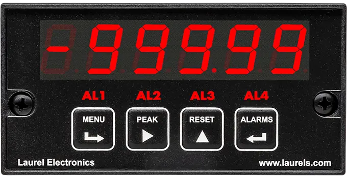
DC Voltage & Current Input Signal
Accuracy of 0.01% of reading ± 2 counts. High read rates at up to 60 or 50 conversions per second.
DC Voltage & Current Input Signal
Accuracy of 0.01% of reading ± 2 counts. High read rates at up to 60 or 50 conversions per second.
Load Cell Strain Gauge and Microvolt
Accuracy of 0.01% of reading ± 2 counts. High read rates at up to 60 or 50 conversions per second.
Scale Meter for Weighing
Accuracy of 0.01% of reading ± 2 counts. High read rates at up to 60 or 50 conversions per second.
Process and Ratiometric
Accuracy of 0.01% of reading ± 2 counts. High read rates at up to 60 or 50 conversions per second.
True RMS AC Voltage & Current
Accuracy of 0.01% of reading ± 2 counts. High read rates at up to 60 or 50 conversions per second.
Thermocouple Temperature
Accuracy of 0.01% of reading ± 2 counts. High read rates at up to 60 or 50 conversions per second.
RTD Temperature
Accuracy of 0.01% of reading ± 2 counts. High read rates at up to 60 or 50 conversions per second.
Ohmmeter for Resistance in Ohms
Accuracy of 0.01% of reading ± 2 counts. High read rates at up to 60 or 50 conversions per second.
Industrial digital panel meters with analog inputs convert a continuously variable electrical or process signal into a precise numeric display, built for mounting directly in a control panel. The "analog input" side covers DC voltage and current, true-RMS AC, load cell and strain gauge output, 4-20 mA and 0-10 V process loops, thermocouple and RTD temperature, and resistance — every one of them a signal that varies smoothly rather than arriving as pulses. Laurel builds all eight configurations on one modular 1/8 DIN platform, so the same main module, power supply board, and setup software carry across the entire line; only the signal conditioner board changes to match the input being measured.
A higher digit count allows a finer-resolution readout of the same signal — a 6-digit display can show more decimal places or a wider full-scale range than a 5-digit display without losing resolution. The underlying measurement accuracy is set by the signal conditioner board itself; the digit count determines how precisely that measurement can be displayed.
Start with the physical signal you're measuring: DC voltage or current calls for the DC configuration, a load cell calls for the load cell configuration (or scale/weighing for a dedicated scale application), a 4-20 mA or 0-10 V loop calls for the process configuration, AC power monitoring calls for true-RMS, and temperature sensing calls for thermocouple or RTD depending on the sensor type already installed.
Solar inverters and wind turbines often produce AC output with switching-related harmonic content rather than a clean sine wave. An average-responding meter misreads that kind of waveform, while a true-RMS meter reports the actual heating-equivalent value regardless of waveform shape, which is why true-RMS configurations are specified for this application.
Generally yes — since the signal conditioner board determines the input type on this modular platform, reconfiguring typically means swapping that board rather than replacing the whole meter, though the correct replacement board depends on which input type it's being changed to.
Both start from the same low-level microvolt input stage, but the scale/weighing configuration adds tare and zero functions purpose-built for an operator running a scale, while the load cell/strain gauge configuration is the more general-purpose version suited to force and material-testing measurement.
It still matters, since isolation protects the meter's own signal integrity from noise on the power or ground system even with a single instrument installed; its benefit becomes more pronounced as more instruments share a panel and a common ground, where isolation prevents one device's noise or fault from affecting another.
Yes, with the appropriate option board. A meter can retransmit its reading as a scaled analog output, trigger relay outputs from configurable setpoints, and communicate digitally over RS-232, RS-485, Modbus RTU, Modbus TCP/IP, or Ethernet.
Confirming the meter's input range and scaling configuration match the actual connected sensor or signal source is the first step, since a mismatch between the configured range and the real signal produces a plausible-looking but incorrect reading rather than an obvious fault.
Confirming the board's exact model and part number matches what the meter was originally configured for is the first step, since boards for different analog input types are physically similar but not interchangeable, and an incorrect type will power up and display something without producing a correct reading.
This can happen when the two instruments measure at different points in the circuit, or when one of them isn't a true-RMS device; confirming both measurement points and both instruments' measurement method (true-RMS vs. average-responding) is the standard first check before assuming either reading is wrong.
Gradual drift is commonly linked to temperature affecting the load cell itself or its cabling rather than the meter; checking for thermal exposure at the load cell and confirming cable shielding and connections are intact is the standard first step.
Confirming the setpoint value, hysteresis, and relay mode (normally open vs. normally closed) are configured as intended is the first step, since a relay that appears not to trigger is often configured correctly but for a different condition than expected.
This typically points to the analog output's own scaling being configured independently from the display scaling, since the two are set up separately; verifying the analog output's high and low endpoints match the intended range is the standard first check.
Verifying the communication protocol, baud rate, and address settings configured in the meter match what the PLC or SCADA system expects is the standard first check, since a mismatch in any one of these will prevent communication even when the physical wiring is correct.
