New Front Panel USB-C Port Coming Soon!
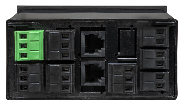
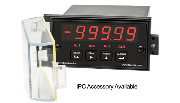
The DC signal conditioner board can used in lieu of the load cell signal conditioner board, be set to ratiometric operation, and be used with the meter's 5 Vdc or 10 Vdc excitation. It's most sensitive full-scale range is ±200 mV with 10 µV resolution, while the load cell signal conditioner board offers most sensitive ranges of ±20 mV and ±50 mV, both with 1 µV resolution. Meters with both boards offer an accuracy of 0.01% of full scale ± 2 counts.
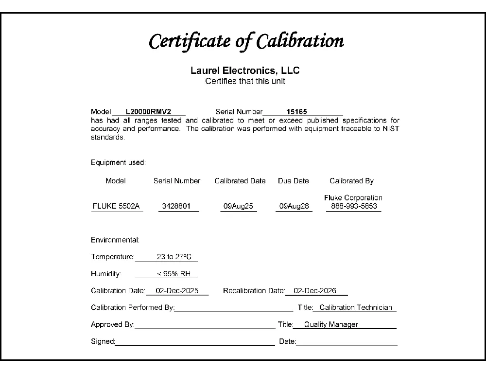
All signal conditioner board ranges are factory-calibrated, with calibration factors for each range securely stored in an onboard EEPROM. These factors can be scaled via software to accommodate external shunts, enabling field replacement of signal conditioner boards without necessitating recalibration of the associated digital panel meter. For optimal accuracy, factory recalibration is recommended annually. All Laurel Electronics instruments undergo factory calibration using the industry-leading Fluke calibrators, which are recalibrated yearly and certified traceable to national standards, ensuring the highest level of precision and reliability.
Scaling is from -99,999 to +99,999 (five full digits) with any decimal point to display readings in engineering units, such as PSI. Three scaling methods are user selectable: scale and offset, two-point method, and system-level calibration using actual transducer signals.
Digital panel meter accuracy in ratiometric bridge operation is 0.01% of reading ± 2 counts. Custom curve linearization, which is available with the optional Extended main board, can extend the working range of load cells. Custom curve linearization also allows greater accuracy to be achieved with lower cost, less linear load cells.
A built-in isolated excitation supply can provide up to 120 mA of current at 10V to power four 350-ohm load cells in parallel. The digital panel meter operates in a ratiometric mode to eliminate errors due to supply variations. When excitation sense inputs are used in 6-wire connection, the digital panel meter compensates for variation in resistance of the transducer leads, thereby allowing long cable runs.
Display & Setpoint Functions for Weighing Applications
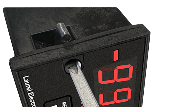
Easy USB-C Programming: Configure a Laureate digital panel meter through the front-panel USB-C port with Laurel’s free Instrument Setup Software for Windows. Meters with a data interface board can also be programmed through that interface. The software shows only the settings that apply to your installed option boards, and configurations can be saved to the meter, a PC, a file server, or a USB thumb drive. Laurel’s free Instrument Setup Software can also be used for light-duty data collection.
Easy scale calibration is achieved using a simple two-point calibration method. First, the desired LO IN reading is set to 0, and the desired HI IN reading is set to a desired value. With no weight on the scale, a button is pushed for LO IN. With a known weight on the scale, that button is pushed again for HI IN. The digital panel meter then automatically computes scale and offset for readout up to five digits in weight units.
High read rate of up to 50 or 60 conversions per second, the Laureate™ Digital Panel Meter uses Concurrent Slope (US Pat. 5,262,780) analog-to-digital conversion to integrate signals over a full power line cycle (50 Hz or 60 Hz). This read rate enables peak and valley capture, real-time computer interfacing, and control applications. Peak and valley values are automatically captured and can be viewed using Laurel’s free Instrument Setup Software (compatible with Windows PCs) or transmitted as serial data.
Scale and offset can be provided by either of two user-selectable methods:
Peak and valley values are automatically captured. These may be displayed via a front panel pushbutton command or control signal at the rear connector, or be transmitted as serial data.
Two rear panel control Inputs (CMOS/TTL levels, logic 0 = tied to digital ground, logic 1 = open) or dry contacts that can be set to control / activate 14 meter commands.
An (isolated) 5, 10, 12, or 24 Vdc excitation output is standard to power transducers or two-wire transmitters. Ratiometric operation, which automatically compensates for changes in the applied excitation, is jumper selectable for applications, such as bridges, where the signal to be measured is proportional to the excitation level.
| Full-Scale Input | Input Impedance | Zero Adjust | Span Adjust | Error at 25°C |
|---|---|---|---|---|
| ± 200.00 mV | 1 GΩ | |||
| ± 2.0000 V | 1 GΩ | -99,999 | 0 to | 0.01% FS |
| ± 20.000 V | 10 MΩ | to +99,999 | ±99,999 | ± 2 counts |
| ± 20.000 mA | 10 Ω | |||
| Recalibration: All ranges are calibrated at the factory. Recalibration is recommended every 12 months. | ||||
| Display | |
|---|---|
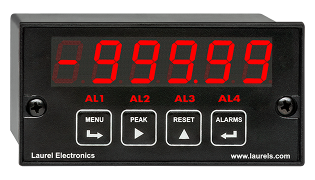
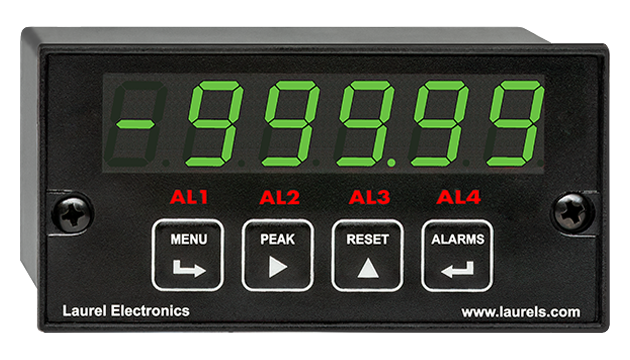
| Readout | 5 LED digits, 7-segment, 14.2 mm (.56"), red or green |
| Range | -99999 to +99999 |
| -999990 to +999990 (with fixed selectable right-hand zero) | |
| Rounding | Count by 1, 2, 5, 10, 20, 50, 100 |
| Indicators | Four LED lamps |
| Accuracy | |
| Error at 25°C | 0.01% FS ± 2 counts |
| Span tempco | 0.0015% of reading/°C |
| Zero tempco | 0.1 µV/°C (use auto-zero when temperature changes) |
| Calibration Method | 2 points using zero weight and known weight |
| Noise Rejection | |
| CMR, DC to 60 Hz | 130 dB |
| NMR at 50/60 Hz | 90 dB with min filtering |
| A-to-D Conversion | |
| Technique | Concurrent Slope (Pat 5,262,780) |
| A-to-D rate | 60/s at 60 Hz, 50/s at 50 Hz |
| Output update | 56/s at 60 Hz, 47/s at 50 Hz |
| Display update | 3.5/s at 60 Hz, 3/s at 50 Hz |
| Power Supply Boards (one required) | |
| Voltage, standard | 85-264 Vac or 90-300 Vdc |
| Voltage, optional | 12-32 Vac or 10-48 Vdc |
| Frequency | DC or 47-63 Hz |
| Power consumption (typ. with four 350Ω load cells at 10V) | 2.4W @ 120 Vac, 2.7W @ 240 Vac, 2.5W @ 10 Vdc, 2.6W @ 20 Vdc, 2.75W @ 30 Vdc, 3.0W @ 40 Vdc, 3.35W @ 48 Vdc |
| Power Isolation | 250V rms working, 2.3 kV rms per 1 min test |
| Excitation Output (standard) | |
| 5 Vdc | 5 Vdc ± 5%, 100 mA (jumper selectable) |
| 10 Vdc | 10 Vdc ± 5%, 120 mA (jumper selectable) |
| 12 Vdc | 12 Vdc ± 5%, 100 mA (jumper selectable) |
| 24 Vdc | 24 Vdc ± 5%, 50 mA (jumper selectable) |
| Output Isolation | 50 Vdc from signal ground |
| Ratiometric operation | Automatically compensates for changes in excitation level. |
| Analog Output Board (one optional) | |
| Output levels | 4-20 mA, 0-20 mA, 0-10V |
| Current compliance | 2 mA at 10V ( > 5 kΩ load) |
| Voltage compliance | 12V at 20 mA (< 600 Ω load) |
| Scaling | Zero and full scale adjustable from -99999 to +99999 |
| Resolution | 16 bits (0.0015% of full scale) |
| Isolation | 250V rms working, 2.3 kV rms per 1 min test |
| Relay Output Boards (one optional) | |
| Dual magnetic relays | 2 Form C, 10A max, 440Vac or 125Vdc max, 2500VA or 300W |
| Quad magnetic relays | 4 Form A (NO), 10A max, 440Vac or 125Vdc max, 2500VA or 300W |
| Dual solid state relays | 2 Form A (NO), AC or DC, 0V - 400V, 120Ma, 35Ohms (max at On-State) |
| Quad solid state relays | 4 Form A (NO), AC or DC, 0V - 400V, 120Ma, 35Ohms (max at On-State) |
| Relay commons | Isolated commons for dual relays or each pair of quad relays |
| Relay isolation | 250V rms working, 2.3 kV rms per 1 minute test |
| Relay latching modes | Latching or non-latching |
| Relay active modes | Active on or off, active high or low |
| Hysteresis modes | QA passband mode, split hysteresis, span hysteresis |
| Communication Boards (one optional) | |
| Board selections | RS232, RS485 with dual RJ11 connectors, RS485 with dual RJ45 connectors, USB, USB-to-RS485 gateway, WiFi with built-in antenna plus USB & RS485, WiFi with external antenna plus USB & RS485 |
| Protocols | Modbus RTU, Modbus ASCII, Modbus TCP (Ethernet), Laurel ASCII |
| Digital addresses | 247 (Modbus), 31 (Laurel ASCII), |
| Isolation | 250V rms working, 2.3 kV rms per 1 min test |
| Environmental | |
| Operating temperature | -40°C to 70°C (-40°F to 158°F) |
| Storage temperature. | -40°C to 85°C (-40°F to 185°F) |
| Relative humidity | 95% at 40°C, non-condensing |
| Protection | NEMA-4X (IP-65) when panel mounted |
| Mechanical | |
| Enclosure | 1/8 DIN, high impact plastic, UL 94V-0, color: black |
| Mounting | 1/8 DIN panel cutout required: 3.622" x 1.772" (92 mm x 45 mm). |
| Dimensions | 4.68" x 2.45" x 5.64" (119 mm x 62 mm x 143 mm) (W x H x D) |
| Maximum panel thickness | 4.5 mm (0.18") |
| Tightening Torque - Connectors | Screw terminal connectors: 5 lb-in (0.56 Nm) |
| Tightening Torque - Pawls | Digital Panel Meter Case Pawls: 5 lb-in (0.56 Nm) |
| Weight of base meter | 210 g (7.4 oz) typical (DPM, counter, timer, 6-digit remote display) |
| Weight of option boards | 30 g (1.0 oz) typical per board (analog output, relay output, communications) |
| General | |
| Programming Methods | Four front panel buttons or via Laurel's free Instrument Setup Software, which runs on a PC under MS Windows. |
| Security | Lockout options include using the front panel buttons, the free Instrument Setup Software, or a hardware jumper. |
| Warranty | 3 years parts & labor |
| Recalibration: All ranges are calibrated at the factory. Recalibration is recommended every 12 months. | |
|
|
| 1/8 DIN Digital Panel Meters | DIN Rail Transmitters |
Free Downloadable Windows-based Instrument Setup (IS) software (Data Interface Board Required) for use with our programmable Digital Panel Meters, Scale Meters, Counters, Timers, Remote Displays, and Transmitters, are an easy method to set up Laureate 1/8 DIN digital panel meters, counters, timers, remote displays, and DIN-rail transmitters, as explained in the Instrument Setup Software Manual. Laureate 1/8 DIN instruments can also be set up from the front panel, as explained in their respective Owners Manuals. Instrument Setup software is of benefit whether or not the PC is connected to the instrument.
Set User Account Control (UAC) of MS Windows to "Never notifiy me" so that Instrument Setup Software can create directories. The UAC change screen can be reached as follows:
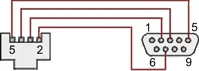
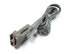
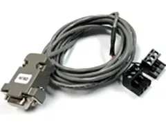
RJ11-to-DB9 cable with rear view of DB9 connector to PC
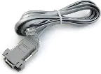
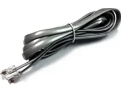
RS232 cable, meter to PC, P/N CBL01
Laureate 1/8 DIN Laureate instruments must be equipped with a serial communications board and be connected to the computer via a serial communications cable. The connection can be via RS232, RS485, USB or Ethernet. Following setup, the serial communications board may be removed from the instrument if desired. The wiring of the RS232 cable is illustrated above with end views of the two connectors.
Laureate LT Series transmitters come standard with a 3-wire serial interface, which can be jumpered for RS232 or RS485.
Laureate LTE Series transmitters come standard with an Ethernet interface.
Click on any of the reduced screens below for a full-size screen view, then click on the Back button of your browser to return to this page. The screens examples below are for a fully-loaded Series 2 Digital Panel Meter (DPM), which is connected to the PC via RS232. If the meter is a Series 1 meter (pre-2007), this is sensed by the software, and somewhat different screens are brought up. Please see Series 1 setup screens.


From the Main Menu, click on Readings if your PC is connected to the meter. A pull-down menu then offers three choices: List, Plot and Graph.


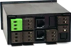


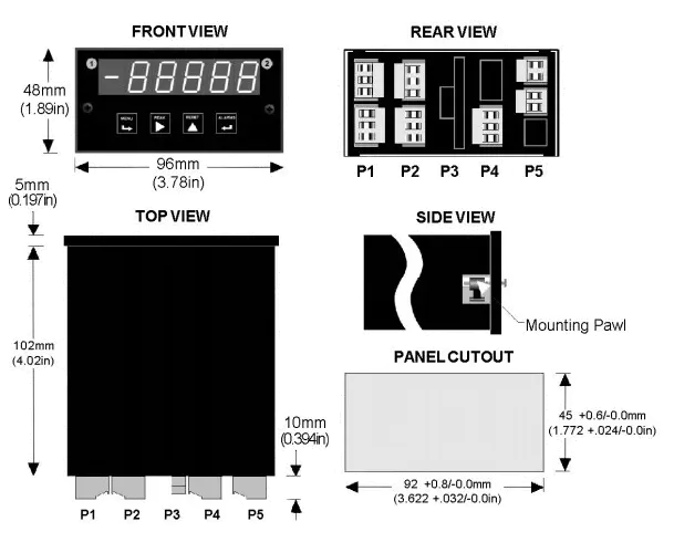
Maximum panel thickness: 4.5 mm (0.18")
Weight of base meter: 210 g (7.4 oz) typical (DPM, counter, timer, 6-digit remote display)
Weight of option boards: 30 g (1.0 oz) typical per board (analog output, relay output, communications)
Tightening Torque - Connectors: Screw terminal connectors: 5 lb-in (0.56 Nm)
Tightening Torque - Pawls: Digital Panel Meter Case Pawls: 5 lb-in (0.56 Nm)
Dimensioned CAD assembly drawings in EPRT, STEP, x_t. dwg, pdf file formats: Laureate-meter-case.zip (zipping prevents browser from opening CAD files as text files).
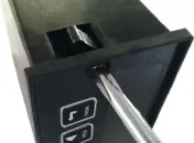 Slide the meter into a 45 x 92 mm 1/8 DIN panel cutout. Ensure that the provided gasket is in place between the front of the panel and the back of the meter bezel.
The meter is secured by two pawls, each held by a screw, as illustrated. Turning each screw counterclockwise extends the pawl outward from the case and behind the panel. Turning each screw clockwise further tightens it against the panel to secure the meter.
Slide the meter into a 45 x 92 mm 1/8 DIN panel cutout. Ensure that the provided gasket is in place between the front of the panel and the back of the meter bezel.
The meter is secured by two pawls, each held by a screw, as illustrated. Turning each screw counterclockwise extends the pawl outward from the case and behind the panel. Turning each screw clockwise further tightens it against the panel to secure the meter.
Turning each screw counterclockwise loosens the pawl and retracts it into its well. This position allows installed meter to be removed from their panel, or new meters to be installed in a panel. Do not remove the screws from their pawls. Doing so would cause the screw and pawl to fall off and likely get lost. Do not overtighten so as not to damage the plastic parts.
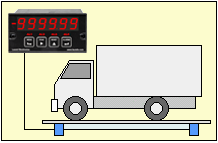
The Laureate weight meter power all four 350 ohm load cells of the scale with its 10 V, 120 mA isolated excitation output. Six-wire connection eliminates the effects of lead resistance and allows long cable runs from the control room to the scale.
The five-digit meter can be scaled to display truck weight up to 99,999 lbs with 1 lb resolution or 999,990 lbs with 10 lb resolution. Accuracy is 0.01% of full scale at 25°C. To avoid the effects of system-level noise, different filter settings as well as "count by" of 1, 2, 5, 10, 20, 50 or 100 with rounding are selectable.
To read out net weight of the load, the truck can first be weighed empty, and this weight can be entered as tare at the push of a button in an auto-tare mode. Or the nominal tare value of the truck can be entered manually. Display of net weight or gross weight is at the push of a button. The gross weight and net weight can be alarmed, be transmitted to a computer via RS232 or RS485, or be transmitted via a 4-20 mA analog signal.
CAL-Analog
Certificate of Calibration
$65.00DLS-XLOG2
XLog2 Data logging Software
$495.00IPC
Digital Panel Meter Splashproof Cover
$55.00CASE1
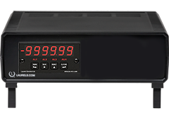
Digital Panel Meter Benchtop Case1
$150.00CASE2
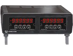
Digital Panel Meter Benchtop Case2
$150.00BOX1
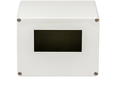
DPM Enclosure Nema-4x Box1
$180.00BOX2
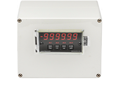
DPM Enclosure Nema-4x BOX2
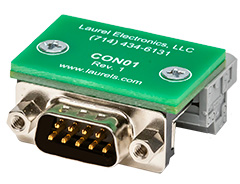
$230.00CON01
CON01 Connector
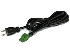
$75.00CBL6
6-foot Power Cable
$41.00CBL12
12-foot Power Cable
$47.00CBL01
RS232 Cable for Meters
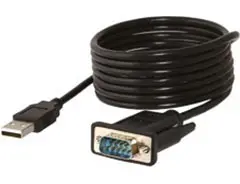
$35.00CBL02
USB-to-RS232 Adapter Cable
$47.00CBL04
RS232 Cable for LT Transmitters
$47.00CBL05
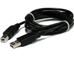
USB Data Cable for Meters
$47.00CBL06
USB-to-RS485 Adapter Cable
$47.00CBL07
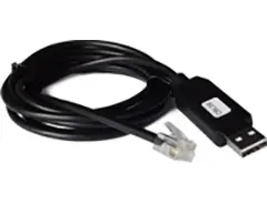
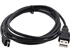
USB Programming & Data Cable
$47.00CBL08
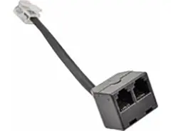
RS485 Splitter Cable
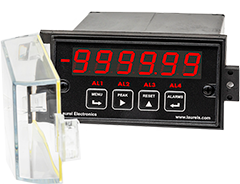
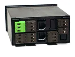
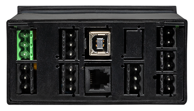
$33.00All boards are isolated from meter and power grounds. Optional Plug-in-Play boards for communications and control include Ethernet, WiFi, serial communication boards, dual or quad relay boards, and an analog output board. Laureates may be powered from 85-264 Vac or optionally from 12-32 Vac or 10-48 Vdc. The display is available with bright red or green 0.56" (14.2mm) high LED digits. The 1/8 DIN case meets NEMA 4X (IP65) specifications from the front when panel mounted. Any setup functions and front panel keys can be locked out for simplified usage and security. A built-in 5, 10, 12, or 24 Vdc excitation supply can power transducers, eliminating the need for an external power supply. All power and signal connections are via UL / VDE / CSA rated screw clamp plugs.
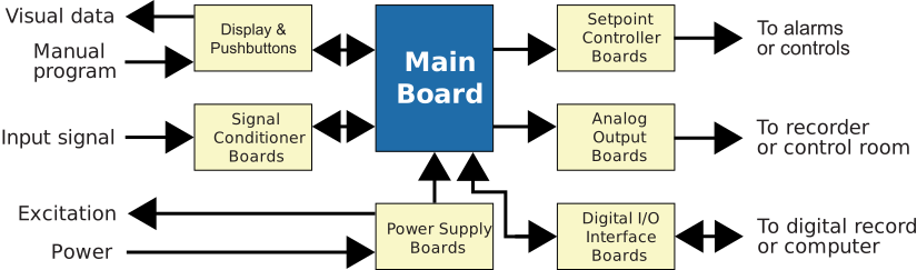
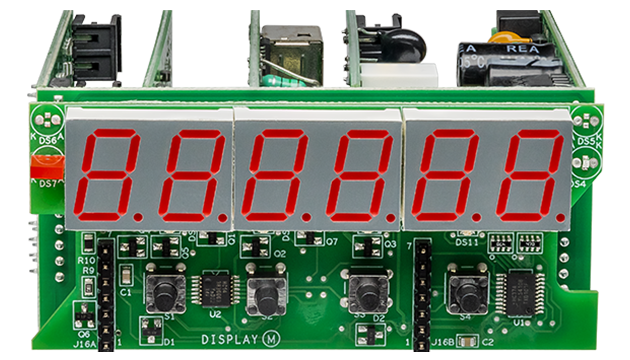
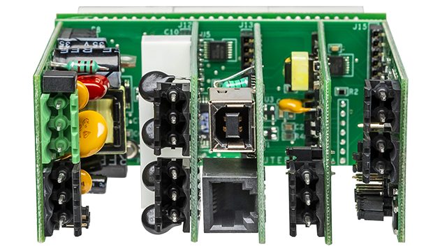
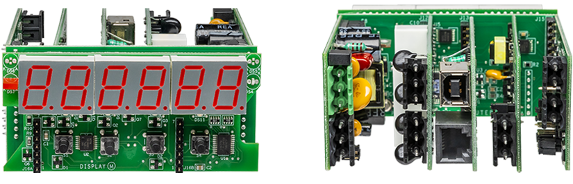
The design of the Laureate™ Series is modular for maximum flexibility at minimum cost. All boards are isolated from meter and power grounds. The base configuration for a digital panel meter or counter consists of a main module (with computer and plug-in display boards), a power supply board, and a signal conditioner board. Optional plug-in-play boards include an isolated setpoint controller board, an isolated analog output board, and an isolated digital interface board. Modular design and a choice of plug-in options allow the Laureate to be customized for a broad range of applications from simple monitoring to control and computer interface. There can be up to five plug-in boards in a 1/8 DIN Laureate.
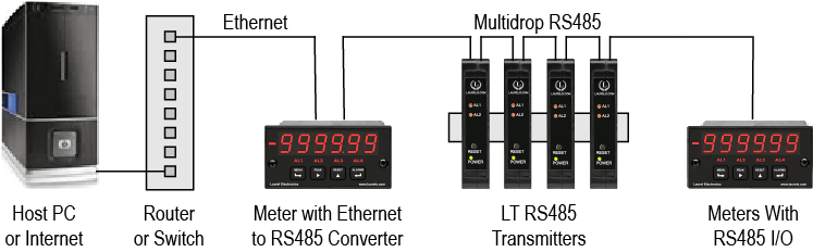
Up to 30 Laureate Digital Panel Meter and/or LT Transmitters can be configured for RS485 and daisy-chained to an LT Transmitter using Laurel’s High Speed Ethernet-to-RS485 converter board for seamless LAN integration. Alternatively, Laurel LTE series Ethernet transmitters can connect directly to a LAN via an Ethernet cable. Setup for both configurations is streamlined using Laurel’s free Instrument Setup Software, which simplifies node discovery and transmitter configuration.
The Laureate Digital Panel Meter can be equipped with Laurel communication boards to support various interfaces and protocols. These include serial interfaces with ASCII or Modbus RTU protocols, and Ethernet interfaces with web access, ASCII, or Modbus TCP/IP protocols, ensuring versatile connectivity for your commercial applications.
The Laureate™ Digital Panel Meter for scale and weighing applications is a compact, inexpensive, and extremely accurate meter with special firmware for weighing, available with the Laureate load cell or DC signal conditioner board. If special weighing firmware isn't needed, the Laureate load cell meter or process meter can be considered instead.
The DC signal conditioner board can be used in place of the load cell board, set to ratiometric operation, and used with the meter's 5 Vdc or 10 Vdc excitation. Its most sensitive full-scale range is ±200 mV with 10 µV resolution, while the load cell board offers more sensitive ranges of ±20 mV and ±50 mV, both with 1 µV resolution. Meters with either board offer 0.01% of full scale ± 2 counts accuracy.
Error at 25°C is 0.01% FS ± 2 counts; span tempco is 0.0015% of reading/°C; zero tempco is 0.1 µV/°C (auto-zero is recommended to compensate as temperature changes). CMR is 130 dB (DC to 60 Hz); NMR is 90 dB at 50/60 Hz with minimum filtering. Concurrent Slope (Pat. 5,262,780) A/D conversion achieves 60/s (60 Hz) or 50/s (50 Hz) read rates, with output update at 56/s or 47/s and display update at a legible 3.5/s or 3/s.
An unfiltered selection provides true peak/valley readings for control applications. A batch average filter averages each 16 conversions. An adaptive moving average filter offers 8 time constants from 80 ms to 9.6 seconds, briefly switching to the shortest constant on a significant signal change before reverting, with an Auto setting selecting based on signal noise.
The meter powers all four 350-ohm load cells of a scale with its 10V, 120 mA isolated excitation output. Six-wire connection eliminates lead-resistance effects, allowing long cable runs from the control room to the scale. The five-digit meter scales to display truck weight up to 99,999 lbs at 1 lb resolution, or 999,990 lbs at 10 lb resolution. To read net weight, the truck can be weighed empty first (auto-tare) or a nominal tare value entered manually; gross and net weight can be alarmed and transmitted via RS232, RS485, or 4-20 mA.
All signal conditioner board ranges are factory-calibrated, with calibration factors stored in EEPROM. Field replacement of the signal conditioner board doesn't require recalibrating the meter. Factory recalibration is recommended annually.
The DC board's ±200 mV most-sensitive range (versus the load cell board's ±20 mV/±50 mV) means it's less sensitive per count, but it may be preferred when a signal source other than a standard low-millivolt load cell is involved, or when the application's existing infrastructure or signal levels already align with the DC board's ranges — the choice comes down to matching the board to the actual signal source's characteristics.
Yes — these are documented as independent, separately configurable features: setpoint offset shifts when the relay actually triggers relative to the target reading, while count-by controls how the displayed value is rounded — an installation can use both simultaneously, with the offset compensating for mechanical dispense lag while count-by keeps the displayed reading at a practical resolution for the operator.
It's documented as precluding decimal point use entirely — since the dummy zero mode shifts the display to accommodate values up to 999,990 by fixing a zero on the right side of the display, there's no remaining digit position available for a decimal point, meaning applications needing fractional resolution shouldn't use this mode.
Zero tempco describes drift in the baseline zero-point specifically, which is exactly the kind of error the auto-zero function is designed to correct — auto-zero periodically re-references the zero point when the meter rests within a small window near zero, directly counteracting zero-point drift, while span tempco (a scale-factor drift) isn't addressed by this same mechanism and would require different compensation.
The documented application specifically emphasizes long cable runs from the control room to the scale — six-wire connection's excitation sense compensation for lead resistance becomes increasingly important as cable length increases, since a longer run has proportionally more resistance to compensate for; a short benchtop connection wouldn't accumulate meaningful lead resistance error the way a long truck-scale cable run would.
This is documented as a setup/scaling choice using the fixed right-hand dummy zero feature, not a hardware change — the same five-digit display and underlying meter hardware supports either configuration, with the choice depending on whether the application needs fine 1 lb resolution within a smaller maximum, or coarser 10 lb resolution to accommodate heavier truck weights within the same five physical digits.
The filter is documented as specifically designed to distinguish this: it briefly switches to the shortest time constant when a genuinely significant signal change occurs (such as a truck driving onto the scale) to track that real change quickly, then reverts to the selected steady-state time constant — this is intended behavior for tracking genuine load changes, not a false-reading risk, though very brief transient bumps during loading could still influence the reading during that fast-tracking window.
It's documented as simply toggling the display view — the tare value (whether from auto-tare or manual entry) is stored and remains in memory, and pressing Reset switches between showing gross weight (total) and net weight (gross minus the already-stored tare), without needing to re-tare or re-enter anything each time the display is toggled.
The meter's modular board architecture generally supports installing both a communication board and an analog output board simultaneously (along with a relay board), so the documented transmission options for the truck weighing application aren't necessarily exclusive — a specific configuration could combine serial data transmission for logging with a simultaneous 4-20 mA output for a separate display or control system, depending on which boards are installed.
The documented range is deliberately narrow — only 0 to 9 counts — meaning auto-zero only re-references the zero point when the meter is already resting extremely close to zero, well below any weight that would represent a genuine load; a real object placed on the scale would produce a reading far outside that narrow window and wouldn't be mistaken for drift, which is why the feature can safely run continuously without an operator needing to disable it before each use.
Documented calibration practice specifically distinguishes these: a corner test involves placing certified test weights at each corner or load point of the scale to verify each individual load cell or section responds correctly, while a section test applies weight across an entire section of a multi-section scale (documented with minimum weights like 30,000 lbs) to verify that section's overall accuracy — both are part of a thorough calibration but check different things.
Documented guidance specifically explains that load points (individual load cells) are calibrated to ensure each section registers exactly the same weight within specified tolerances, rather than only checking against a single certified weight — since a truck scale's accuracy depends on all load cells agreeing with each other as much as with an absolute reference, testing individual load cells catches problems that a single overall weight check might miss.
Documented industry guidance specifically recommends at least once per year for typical use, increasing to quarterly for heavy-use scales, particularly those used in legal-for-trade applications — the underlying rationale is that heavier use accelerates wear and increases the chance of accuracy drift, so the same annual baseline isn't appropriate for every installation.
Yes — documented practice specifically describes an "end-middle-end" test: weighing a piece of mobile equipment (such as a loader or a site vehicle) with a known, recorded weight and fuel level, then driving it across the scale weekly, stopping at each end and the center, and comparing readings against the known baseline weight — this is documented as a practical way to catch developing problems between full calibration visits.
Documented guidance specifically identifies mud and debris buildup underneath a weighbridge as a real, common accuracy problem — physical material collecting under or around the scale structure can interfere with proper load transfer to the load cells, producing inaccurate readings that have nothing to do with the load cells or electronics themselves, and would only be caught through visual inspection and cleaning rather than electronic recalibration.
Documented best practice specifically flags environmental conditions during calibration as a factor affecting result validity — wind or extreme weather can introduce forces on the scale platform or test weights beyond the actual weight being measured, or affect technician safety and precision during a process that requires careful, controlled placement of certified test weights.
Yes — documented practice specifically notes that established calibration service companies typically have their own test weights certified and adjusted every year or every other year, and recommends requesting certification documentation for the specific weights a service provider intends to use, since a truck scale calibration is only as trustworthy as the reference weights used to perform it.
Documented guidance specifically frames NTEP certification as requiring ongoing maintenance, not a one-time achievement — regular calibration and maintenance checks are documented as essential to maintaining NTEP standards over the scale's operational life, since a scale that drifts out of specified tolerances after initial certification would no longer genuinely meet the legal-for-trade accuracy requirements the certification represents.