
DC Voltage and Current Input Signal
Accuracy of 0.01% of reading ± 2 counts. High read rates at up to 60 or 50 conversions per second.
DC Voltage and Current Input Signal
Accuracy of 0.01% of reading ± 2 counts. High read rates at up to 60 or 50 conversions per second.
Load Cell Strain Gauge and Microvolt
Accuracy of 0.01% of reading ± 2 counts. High read rates at up to 60 or 50 conversions per second.
Scale Meter for Weighing
Accuracy of 0.01% of reading ± 2 counts. High read rates at up to 60 or 50 conversions per second.
Process and Ratiometric
Accuracy of 0.01% of reading ± 2 counts. High read rates at up to 60 or 50 conversions per second.
True RMS AC Voltage & Current
Accuracy of 0.01% of reading ± 2 counts. High read rates at up to 60 or 50 conversions per second.
Thermocouple Temperature
Accuracy of 0.01% of reading ± 2 counts. High read rates at up to 60 or 50 conversions per second.
RTD Temperature
Accuracy of 0.01% of reading ± 2 counts. High read rates at up to 60 or 50 conversions per second.
Ohmmeter for Resistance in Ohms
Accuracy of 0.01% of reading ± 2 counts. High read rates at up to 60 or 50 conversions per second.
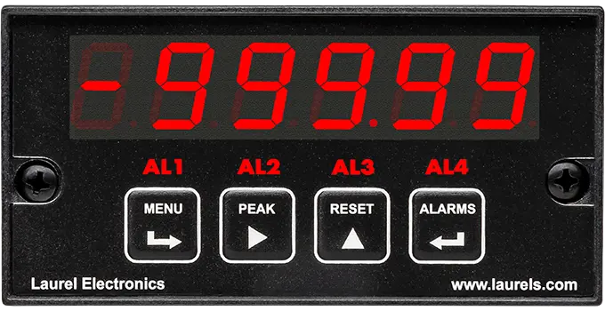
An electronic analog panel meter is a digital-readout instrument mounted in the face of a control panel to measure an analog input signal — DC voltage or current, true-RMS AC, load cell and strain gauge output, process loop signals like 4–20 mA, thermocouple or RTD temperature, or resistance — and display it as a precise numeric value. The word "analog" here refers to the type of input signal being measured, not to a moving-pointer display: the instrument itself is fully electronic, with a digital LED or LCD readout, an internal analog-to-digital converter, and the same modular 1/8 DIN board architecture used across Laurel's meter, counter, and timer lines. That architecture is what lets one base platform be configured for load cell weighing, process indication, true-RMS power monitoring, or temperature measurement simply by changing the signal conditioner board.
The "analog" refers to the nature of the input signal being measured — a continuously variable signal such as DC voltage, 4–20 mA, or a load cell's millivolt output — not to the display itself. The instrument converts that analog signal to a digital value internally and shows it on a digital LED or LCD readout, so the display is fully electronic even though the term "analog" describes the input side.
The load cell, strain gauge, and microvolt configuration is the general-purpose low-level signal amplifier suited to force and material-testing measurement, while the scale/weighing configuration adds tare and zero functions specifically built for industrial scale readouts. Both start from the same low-level input stage; the weighing version is tailored to the workflow of a scale operator.
The DC voltage/current configuration is a straightforward measurement of a DC signal for general indication, while the process/ratiometric configuration is built around process-loop signals such as 4–20 mA and 0–10 V, and can also handle ratiometric or potentiometer-follower inputs used in position and level sensing.
Yes — the signal conditioner board determines the input type, and because the platform is modular, reconfiguring a meter for a different input generally means replacing that board rather than replacing the whole instrument, though the specific board required depends on which input type is being changed to.
Up to five plug-in boards total can be installed in a single 1/8 DIN housing, which includes the signal conditioner and power supply plus up to three further option boards — relay/setpoint, analog output, and digital communications.
No — the relay/setpoint function is an optional plug-in board rather than something built into every configuration, so a meter ordered without that option won't have local alarm relay outputs unless the board is added.
The resistance configuration covers multiple ranges from low ohms up to the megohm range, with ratiometric excitation used to maintain accuracy across the span, making it suited to both precision low-resistance checks and higher-value resistance measurement.
True-RMS measurement is necessary whenever the AC waveform being measured isn't a clean sine wave — such as the output of a variable-frequency drive or other switching load — since an average-responding (non-true-RMS) meter will read those waveforms incorrectly. For loads known to be clean sinusoidal AC, a standard AC configuration may be sufficient, but true-RMS is the safer choice when the waveform isn't guaranteed to be sinusoidal.
Confirming the exact model and board part number against the original order before installing is the first step, since boards for different input types (DC voltage, load cell, process, true-RMS, temperature, resistance) are physically similar but not interchangeable, and installing the wrong type won't produce a correct reading even though it may fit and power up normally.
This typically points to the analog output board's own scaling being configured independently from the display scaling, since the two are set up separately; verifying the analog output's high and low endpoints match the intended range is the standard first check.
Confirming both meters are calibrated to the same reference and configured with identical scaling, zero, and span settings is the first step, since unit-to-unit variation within a normal accuracy tolerance is expected, but a difference beyond that tolerance usually points to a scaling mismatch rather than a hardware fault.
Confirming the setpoint value, hysteresis, and relay mode (normally open vs. normally closed) are configured as intended is the first step, since a relay that appears not to trigger is often configured correctly but for a different condition than expected.
Confirming the configuration wasn't still in a temporary, unsaved state at the time of the outage is the first step, since settings entered through front-panel pushbuttons or setup software need to be saved to take effect permanently; a configuration that was saved before the outage should persist in non-volatile memory through a power loss.
Yes — configuration can be done entirely through front-panel pushbuttons without a PC connected at all; the setup software is a convenience for faster or more detailed configuration, particularly useful for custom curve linearization, but it isn't required for basic setup.
Factory recalibration is recommended annually, though the signal conditioner board's calibration factors are stored in EEPROM, so field-replacing a board doesn't require recalibrating the rest of the instrument.
Since 1/8 DIN is a standardized size (approximately 96 × 48 mm), a panel cutout built to that standard should generally accommodate it regardless of brand, though confirming mounting depth and any panel-specific clearance requirements before installation is the recommended first step.
