
Frequency, Rate, or Period
Time Base Crystal calibrated to ±2 ppm
Span tempco ±1 ppm/°C (typ)
Long-term Drift ±5 ppm/year (typ)
Frequency, Rate, or Period
Time Base Crystal calibrated to ±2 ppm
Span tempco ±1 ppm/°C (typ)
Long-term Drift ±5 ppm/year (typ)
Rate, Totalizer with Functions
Time Base Crystal calibrated to ±2 ppm
Span tempco ±1 ppm/°C (typ)
Long-term Drift ±5 ppm/year (typ)
Pulse Input Totalizer
Time Base Crystal calibrated to ±2 ppm
Span tempco ±1 ppm/°C (typ)
Long-term Drift ±5 ppm/year (typ)
Analog Input Totalizer
Time Base Crystal calibrated to ±2 ppm
Span tempco ±1 ppm/°C (typ)
Long-term Drift ±5 ppm/year (typ)
Batch Controller Pulse Input
Time Base Crystal calibrated to ±2 ppm
Span tempco ±1 ppm/°C (typ)
Long-term Drift ±5 ppm/year (typ)
Batch Controller Analog Input
Time Base Crystal calibrated to ±2 ppm
Span tempco ±1 ppm/°C (typ)
Long-term Drift ±5 ppm/year (typ)
AC Phase, Angle, and Power Factor
Time Base Crystal calibrated to ±2 ppm
Span tempco ±1 ppm/°C (typ)
Long-term Drift ±5 ppm/year (typ)
Quadrature Encoder Input
Time Base Crystal calibrated to ±2 ppm
Span tempco ±1 ppm/°C (typ)
Long-term Drift ±5 ppm/year (typ)
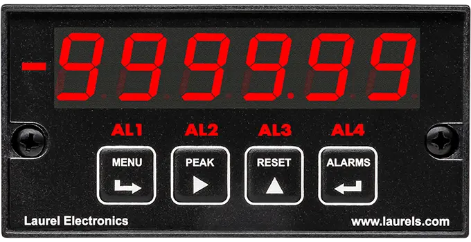
Electronic counters are panel-mounted digital instruments purpose-built to process pulse trains — counting events, computing a rate from pulse timing, totalizing a running sum, or driving batch control relays from a count or total. Unlike a panel meter, which reads a continuous signal such as voltage or temperature, an electronic counter's job starts with discrete pulses: the output of a flow meter, a proximity switch, a tachometer, or a rotary encoder. Laurel's counters share the same 1/8 DIN modular platform as its meters and timers — a main computer/display module, an isolated power supply board, and a signal conditioner board — with a time base crystal calibrated to ±2 ppm and a 6-digit LED display across the line.
A panel meter measures a continuous signal — voltage, current, temperature — and displays its value directly. An electronic counter processes discrete pulses instead, counting them, timing them to compute a rate, or totalizing them into a running sum. The input and the internal processing are fundamentally different even though both share the same panel-mount case format.
A dual-channel configuration can track rate and total simultaneously from the same input, or use its second channel independently, rather than requiring two separate instruments to get both a running total and a live rate reading from one pulse source.
The math function configuration can compute the sum, difference, ratio, or product between two separate input channels, which basic totalizing can't do. This is useful for applications comparing two related signals — inflow versus outflow, mixing ratios, or synchronized rates between two points in a process.
The pulse input totalizer counts discrete pulses directly from a sensor that already outputs pulses. The analog input totalizer instead accepts a continuous analog signal — such as a 4-20 mA flow transmitter — and converts it internally to a pulse rate before totalizing, which is necessary when the source signal isn't already pulse-based.
The first relay handles the primary on/off control of the batch fill. The second relay triggers a slow-approach signal shortly before the target is reached, reducing flow rate to improve shutoff accuracy — a fast fill followed by a controlled, precise finish.
The counter times the interval between zero-crossings of two AC signals (typically voltage and current) and derives phase angle from that timing; power factor is then computed as the cosine of the resulting angle. This timing-based method is what allows fine resolution, down to about 0.01° at low frequencies.
A quadrature encoder outputs two phase-offset pulse channels that together indicate both position or rate and direction. A dedicated quadrature input decodes that two-channel relationship — including X1/X2/X4 counting resolution and a zero index pulse — which a standard single-channel pulse counter input isn't built to interpret.
Yes. With the appropriate option board, a counter can retransmit its rate or total as a scaled analog output, trigger relay outputs from configurable setpoints, and communicate over RS-232, RS-485, Modbus RTU, Modbus TCP/IP, or Ethernet.
Confirming the pulse scaling factor configured in the counter matches the actual output of the connected sensor (such as pulses per gallon or pulses per revolution) is the first step, since an incorrect scaling factor produces a total that's proportionally off rather than randomly wrong.
Confirming the slow-approach relay's trigger point gives the system enough lead time to actually slow the flow before final cutoff is the first step, since overshoot is commonly caused by the slow-approach point being set too close to the target rather than a counter fault; valve or pump response lag should also factor into where that point is set.
Confirming both channels use the same, correctly configured pulse scaling factor is the first step, since a mismatch between channels is more often a configuration difference than an actual difference in the physical flows being measured.
Confirming the A and B channel wiring hasn't been swapped is the first step, since quadrature direction sensing depends on the phase relationship between the two channels, and reversing them inverts the reported direction even though the count magnitude stays correct.
Phase measurement is based on timing between zero-crossings, and at lower frequencies each cycle takes proportionally longer, which can make the measurement more sensitive to small timing variations or waveform distortion; confirming the input signal is clean and free of noise is the standard first check before suspecting the counter.
Checking the input's debounce or filtering settings is the standard first step, since a mechanical switch or noisy pulse source can generate extra transitions the counter interprets as additional pulses; confirming the sensor type matches the input configuration (mechanical contact vs. solid-state) is the next check.
Verifying the communication protocol, baud rate, and address settings configured in the counter match what the PLC or SCADA system expects is the standard first check, since a mismatch in any one of these will prevent communication even when the physical wiring is correct.
