
Features
- Accepts a 4-20 mA, 1-5V, 0-5V or 0-10V input signal
- Drives four (4) independent 4-20 mA outputs proportional to input
- Signal input and outputs can share a common ground
- Remote grounds can differ by up to ±10V from local signal ground
- Opening any output loop does not affect other loops
- ±10 zero and span fine adjustments for each output loop
- Loop current test point for each output, where 200 mV = 20 mA
- Indicator LED for each connected output
- Powered by 10-48 Vdc or 12-32 Vac
- Powers a 2- or 3-wire input transmitter at 24 Vdc at up to 30 mA
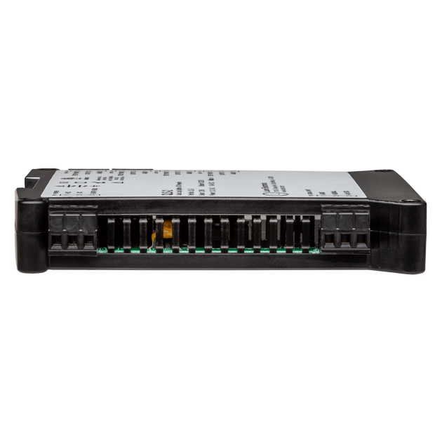
- 22.5 mm (0.9") wide case snaps to 35 mm DIN rail
- Weighs only 159 g (5.6 oz)
- Operating temperature from -40°C to 70°C (-40°F to 158°F)
Certificates of Compliance
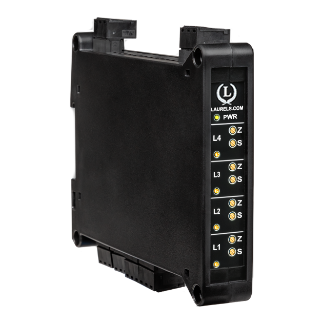
Features of the DIN Rail Transmitter for Quad Current Loop Splitter / Retransmitter
The DIN Rail Transmitter for Quad Current Loop Splitter accepts 4-20 mA, 1-5V, 0-5V, or 0-10V inputs and drives four independent 4-20 mA outputs with ±10V common mode isolation. It supports shared or ±10V differing grounds, with each loop featuring ±10% zero/span adjustments, a 200 mV = 20 mA test point, and an LED indicator. Powered by 10-48 Vdc/12-32 Vac, it powers 2- or 3-wire transmitters at 24 Vdc up to 30 mA. Housed in a 22.5 mm case for 35 mm DIN rail, it weighs 159 g and operates from -40°C to 70°C, with CE, RoHS3, and ETL certifications. The Quad Current Loop Splitter solves series loop issues by providing four adjustable outputs from one input, ensuring unaffected loops if one fails. It includes LED diagnostics and test points, enhancing reliability and ease of use.
The QLS-2 Quad Current Loop Splitter / Retransmitter is factory-calibrated. For optimal accuracy, factory recalibration is recommended annually. All Laurel Electronics instruments undergo factory calibration using the industry-leading Fluke calibrators, which are recalibrated yearly and certified traceable to national standards, ensuring the highest level of precision and reliability.
Problems with Current Loop Loads in Series
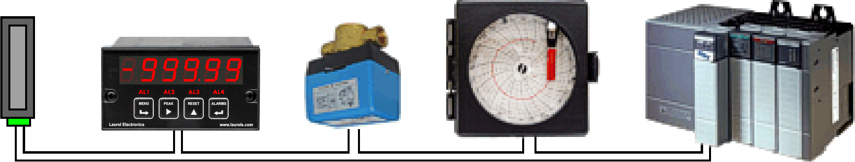
| Common Practice: | A single 4-20 mA loop from a sensor is connector to a panel meter, a control valve, a recorder and a PLC in series. If the loop opens, all devices in the loop fail. |
- All devices in the loop cannot share a common ground, but must be electrically floating. This is often not possible.
- When any device in a loop is removed, fails, or if a wiring fault occurs, all other devices in the loop loose their 4-20 mA signal.
- The transmitter(signal conditioner) voltage compliance limit may be exceeded, since the voltage drops across loads in series are additive.
- The 4-20 mA signal to each load device cannot be individually adjusted for calibration purposes.
- There are not diagnostics for the current to each load.
The Laureate QLS-2 Quad Current Loop Splitter / Retransmitter Solution
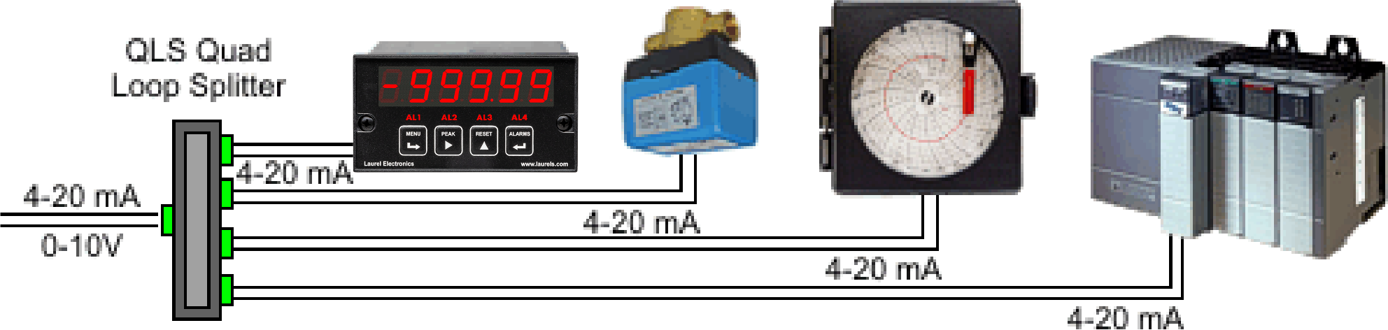
| Improved Practice: | Four independent 4-20 mA loops with ±10V common mode isolation. If any of the output loops opens, only a single device is affected. The output loops can share a common ground. |
- Sources up to four (4) independently adjustable 4-20 mA outputs from a single input, which can be 4-20 mA, 1-5V, 0-5V or 0-10V, as selected by jumpers.
- If any device in an output loop is removed from a loop or fails, or if a wiring fault occurs in any loop, the other loops continue to operate properly.
- Signal input and outputs can share a common signal ground.
- Common mode voltage of output loops is ±10V by means of active circuitry so that remote grounds can vary by up to ±10V.
- Each loop only drives a single load, thus avoiding voltage compliance problems.
- ±10% of zero and span adjustment are provided for each output loop to allow for independent loop calibration.
- Diagnostics for each output loop are provided by a yellow LED lamp to indicate loop continuity and by a test point across a 10Ω series resistor, where 200 mV corresponds to 20 mA. The test point allows a multimeter to measure the loop current without breaking the loop.
- Power for the model QLS-2 Quad Current Loop Splitter / Retransmitter is low voltage 10-48 Vdc or 12-32 Vac. An excitation output is provided on the signal input side to drive a 2- or 3-wire transmitter at 24 Vdc up to 30 mA.
QLS-2 Pinouts and Theory of Operation
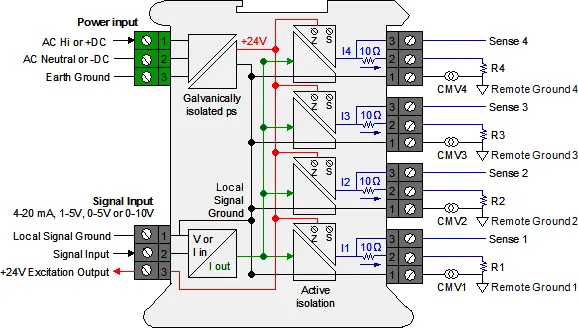
Galvanic & Active Isolation: A single input current loop is split into four independent output loops I1, I2, I3, and I4 by four current generators. The input and output signals are galvanically isolated from power and earth grounds by up to 264 Vac. Active circuitry allows a common mode voltage up to ±10V between Local Signal Ground (on pins 1) and the Remote Grounds. Each common mode voltages, labeled CMV1 to CMV4 in the diagram, reflects the actual voltage difference between Local Signal Ground and the Remote Ground. Such differences can be caused by current flows in the factory.
Floating loads: Any output load R that is floating (not connected to Earth Ground or a Local Ground) can be connected between current output (Pin 1) and current return (Pin 2). Current return is internally tied to Signal Ground, which can be floating or be connected to Earth Ground.
Grounded loads: Any output load R can be connected to a Local Ground instead of current return. The Remote Grounds can each be different, but can only differ from Signal Ground by a safe common mode voltage CMV. Signal Ground should be tied to Earth Ground to minimize noise pickup.
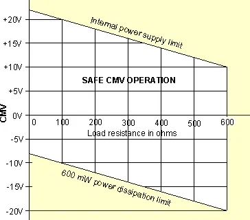
Input-output isolation: If a load R is grounded to a Local Ground, the available common mode voltage CMV is limited on the positive side by the unit's internal power supply and on the negative side by the 600 mW power dissipation limit of an output transistor. The above diagram shows allowable CMV as a function of output load resistance R. For example, with a 250Ω load, CMV can range from -13V to +17V. With a 500Ω load, CMV can range from -18V to +12V. The unit will not work correctly if CMV limits are exceeded or the load resistance is greater than 600Ω.
| Signal Input & Excitation | ||||
|---|---|---|---|---|
| Signal Type | 4-20 mA, 1-5V, 0-5V, 0-10V (jumper selectable) | |||
| Input Resistance | 50Ω for 4-20 mA, 412kΩ for 1-5V, 464kΩ for 0-5V, 935kΩ for 0-10V | |||
| Transducer Excitation | 24 Vdc output, 30 mA max | |||
| Signal Outputs | ||||
| Number of Outputs | 4 | |||
| Signal Type | 4-20 mA | |||
| Signal Ground | Same signal ground for input and outputs | |||
| Common Mode Voltage | Remote signal grounds can be up to ± 10V from local signal ground | |||
| Zero & Span Adjustments | ± 10% for each output with 25-turn potentiometers | |||
| Isolation Power to Signals | 264 Vac | |||
| Voltage Compliance | 12V (600Ω per loop at 20 mA) | |||
| Load Regulation | ± 0.005% of span from 0Ω to 600Ω | |||
| Accuracy | ± 0.02% max span error at 23°C | |||
| Zero Tempco | ± 0.1 µA/°C typical, ± 0.2 µA/°C max | |||
| Span Tempco | ± 10 ppm/°C (0.16 µA/°C) typical, ± 20 ppm/°C (0.32 µA/°C) max | |||
| AC Rejection | 90 dB from DC to 60 Hz | |||
| Response Speed | 2 ms risetime, 7 ms settling time to 0.1% of final value | |||
| Loop Current Sense | 10Ω ± 0.5% series resistor. Generates 200 mV at 20 mA | |||
| Loop Continuity Indication | Yellow LED lamp per loop, brightness proportional to current. | |||
| Power Input | ||||
| Model QLS-1 | 85-264 Vac or 90-300 Vdc | |||
| Model QLS-2 | 10-48 Vdc or 12-32 Vac | |||
| Power Frequency | DC or 47-63 Hz | |||
| Power Isolation | 250V AC working, 1.0 kV AC for 60 sec, 1.7 kV DC for 2 sec | |||
| Power Consumption | 3.5 W max, all loops delivering 20 mA | |||
| Power On Indication | Green LED lamp | |||
| Environmental | ||||
| Operating Temperature | -40°C to 70°C (-40°F to 158°F) | |||
| Storage Temperature | -40°C to 85°C (-40°F to 185°F) | |||
| Relative Humidity | 95% at 40°C, non-condensing | |||
| Cooling Required | Mount transmitters with ventilation holes at top and bottom. Leave 6 mm (1/4") between transmitters, or force air with a fan. | |||
| Mechanical | ||||
| Enclosure | Rugged black polycarbonate housing material | |||
| Mounting | 35 mm rail per DIN EN 50022 | |||
| Dimensions | 129 x 104 x 22.5 mm case | |||
| Connectors | Detachable screw clamp connectors meet VDE / IEC / UL / CSA standards. RJ45 jack for Ethernet | |||
| Tightening Torque | Screw terminal connectors: 5 lb-in (0.56 Nm) | |||
| Weight | Complete transmitter: 183 g (6.5 oz) | |||
| Replacement Case Screws | ||||
| Size | 6 | |||
| Thread Pitch | 6-19 | |||
| Length | 1/2" | |||
| Head Style | Pan Head | |||
| Drive Style | Phillips | |||
| Head Diameter | 0.256-0.270 | |||
| Head Height | 0.087-0.097 | |||
| Full/Partial Thread | Full | |||
| Drive Size | 2 | |||
| Material | Steel | |||
| Finished | Black Oxide | |||
| General | ||||
| Warranty | 3 years parts & labor | |||
| Recalibration: All ranges are calibrated at the factory. Recalibration is recommended every 12 months. | ||||
Dimensions
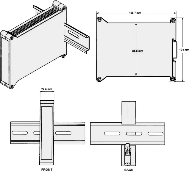
Dimensioned CAD assembly drawings in EPRT, STEP, x_t, .dwg, pdf file formats: Laureate-transmitter-case.zip (zipping prevents browser from opening CAD files as text files).
What is the Laureate QLS-2 Quad Output 4-20 mA Current Loop Splitter / Retransmitter?
The Laureate QLS-2 is a DIN rail-mounted current loop splitter designed specifically for low-voltage DC and AC powered systems. It accepts a single 4-20 mA, 1-5V, 0-5V, or 0-10V input signal and produces four fully independent, isolated 4-20 mA output loops — powered by 10-48 Vdc or 12-32 Vac.
The QLS-2 is the right choice when panel power is 24 Vdc, a standard in building automation, process skids, battery-backed systems, solar installations, and modern low-voltage control panels. Where the QLS-1 is built for high-voltage AC environments, the QLS-2 is purpose-built for the growing number of facilities running on 24 Vdc distributed power.
Like all QLS models, it solves the fundamental problem of series current loop wiring — where a single fault takes down every device sharing that loop — by driving each output from an independent current generator. Opening one output loop has zero effect on the other three.
Why Choose the QLS-2 Over the QLS-1?
Both models are identical in signal performance. The decision comes down to available panel power:
- QLS-2 — 10-48 Vdc or 12-32 Vac. Ideal for 24 Vdc panels, battery systems, solar-powered remote installations, skid-mounted equipment, and any application where high-voltage AC is unavailable or undesirable.
- QLS-1 — 85-264 Vac or 90-300 Vdc. For traditional AC-powered industrial panels.
The QLS-2's wide 10-48 Vdc input range is particularly useful in battery-backed or renewable energy applications where bus voltage may vary. A 24 Vdc nominal system can drop to 20V under load or rise above 28V on charge — the QLS-2 handles this range without issue.
How the QLS-2 Works
Input Signal Selection
The QLS-2 accepts 4-20 mA, 1-5V, 0-5V, or 0-10V input via onboard jumper selection, making it compatible with the full range of standard industrial transmitters and sensors without requiring additional signal conditioning.
Four Independent Output Loops
Four independent current generator circuits each produce a 4-20 mA output proportional to the input. Each loop is galvanically isolated from the power supply. Output ground references can differ from local signal ground by up to ±10V through active common mode compensation — a critical feature in facilities where ground potential differences exist between field devices and control panels.
Per-Loop Calibration and Diagnostics
Each output loop includes a 25-turn potentiometer for ±10% zero and span adjustment, a 10Ω test point resistor (200 mV = 20 mA, readable with a standard multimeter without breaking the loop), and a yellow LED that glows proportionally to loop current. A green LED confirms power is present.
Transmitter Excitation Output
The QLS-2 includes a 24 Vdc excitation output rated at up to 30 mA to power a 2- or 3-wire upstream transmitter directly from the splitter. This eliminates the need for a separate loop power supply and simplifies panel wiring — particularly valuable when the QLS-2 itself is powered from the same 24 Vdc bus.
Where is the QLS-2 Used?
Building Automation and HVAC
Building automation systems standardize on 24 Vdc panel power, making the QLS-2 the natural fit. Pressure differential transmitters, CO₂ sensors, humidity sensors, and airflow transmitters frequently need to feed both the BMS controller and local displays or actuators simultaneously. The QLS-2 distributes one sensor signal to all destinations independently, with per-loop calibration to match each device's input range.
Solar and Renewable Energy Installations
Remote solar and wind installations run on DC bus voltages that vary with battery state and load. The QLS-2's 10-48 Vdc input range accommodates 12V, 24V, and 48V battery systems. Current signals from inverters, charge controllers, or energy meters can be distributed to local displays, dataloggers, and remote SCADA inputs simultaneously without series loop dependency.
Skid-Mounted Process Equipment
Packaged process skids — pumping stations, chemical dosing systems, cooling skids — are commonly engineered with 24 Vdc control power to simplify wiring and meet area classification requirements. The QLS-2 fits directly into these panels, distributing transmitter signals to the skid PLC, the plant DCS, a local panel meter, and a data historian without series wiring.
Battery-Backed and UPS-Protected Systems
Critical monitoring systems that must continue operating through power outages are often fed from 24 Vdc UPS outputs. The QLS-2 operates through the full UPS output range, ensuring that all four output loops remain active even when mains power is lost.
Remote and Off-Grid Monitoring
Pipeline monitoring stations, wellhead instrumentation, water quality monitoring systems, and environmental sensing arrays in remote locations often rely on solar or battery power. The QLS-2 provides multi-point signal distribution at these sites without requiring AC power infrastructure.
OEM Machine Building
Machine builders standardizing on 24 Vdc control architecture can integrate the QLS-2 directly into their panel designs. The compact 22.5 mm DIN rail format, screw-clamp connectors, and wide operating temperature range (-40°C to 70°C) make it well suited for machine cabinets that may be installed in unheated environments.
QLS-2 Specifications
- Power input: 10-48 Vdc or 12-32 Vac, DC or 47-63 Hz
- Input signal: 4-20 mA, 1-5V, 0-5V, or 0-10V (jumper selectable)
- Outputs: Four independent 4-20 mA loops
- Output accuracy: ±0.02% of span at 23°C
- Common mode voltage: ±10V between local and remote signal grounds
- Voltage compliance: 12V per loop (600Ω max load at 20 mA)
- Zero and span adjustment: ±10% per loop, 25-turn potentiometers
- Transducer excitation: 24 Vdc at up to 30 mA
- Power consumption: 3.5W max (all loops at 20 mA)
- Case: 22.5 mm wide, 35 mm DIN rail, 159 g
- Operating temperature: -40°C to 70°C
- Certifications: ETL (Intertek #4006497), CE, RoHS 3
- Warranty: 3 years parts and labor
Conclusion
The Laureate QLS-2 brings the full signal distribution and diagnostic capability of the QLS family to low-voltage DC and AC powered installations. Whether in a 24 Vdc building automation panel, a solar-powered remote monitoring station, or a skid-mounted process system, the QLS-2 provides four independent, calibrated, fault-tolerant 4-20 mA outputs from a single input — in a compact DIN rail package that runs directly from the panel's existing DC power bus.
QLS-2 Quad Current Loop Splitter Frequently Asked Questions
Will the QLS-2 keep all four loops running if my 24 Vdc bus is shared with other equipment drawing power?
As long as the bus stays within the 10-48 Vdc input range and the QLS-2's own 3.5W max consumption is accounted for in the panel's power budget, other equipment sharing the same 24 Vdc bus doesn't affect the splitter's operation — each output loop still runs from its own independent current generator regardless of what else is drawing from the supply.
Can the QLS-2 run directly off a 12V battery system without a boost converter?
Yes — its 10-48 Vdc input range covers 12V, 24V, and 48V nominal battery systems directly, including the voltage sag a 12V battery can see under load, without needing a separate DC-DC converter ahead of the unit.
Does the QLS-2 add meaningful load to a solar or battery-powered installation's power budget?
Power consumption is rated at 3.5W max with all four loops delivering full 20 mA output, which is a small addition to most solar or battery system budgets, though it's still worth including in the overall load calculation for a tightly sized off-grid installation.
Is the QLS-2 a good fit for a skid package that already runs 24 Vdc control power?
Yes — the QLS-2 is specifically built for that scenario, distributing one transmitter's signal to the skid PLC, plant DCS, a local panel meter, and a data historian directly off the skid's existing 24 Vdc control power without adding a separate AC supply to the package.
If my UPS output sags briefly during a transfer, will the QLS-2's output loops glitch?
The unit operates through its full 10-48 Vdc input range, so brief sag within that range during a UPS transfer shouldn't interrupt loop operation; a genuine drop below 10 Vdc, even momentarily, would affect all four loops simultaneously since they share the same power input.
Can I use the QLS-2 in a machine I'm building for both US and European customers?
Yes for the DC side — the 10-48 Vdc input works globally without adjustment for machines standardized on 24 Vdc control architecture; the QLS-2's AC option (12-32 Vac) is a lower-voltage range than the QLS-1's, so confirm which AC voltage your target installations actually use.
How many independent instruments can one QLS-2 feed at a remote or off-grid site?
Up to four — each of the four output loops is independent, so a single transmitter signal at a remote pipeline, wellhead, or environmental monitoring site can feed up to four separate instruments (local display, datalogger, SCADA input, etc.) simultaneously from one QLS-2.
Does the QLS-2 need its own dedicated power supply, or can it share the transmitter's excitation power?
It needs its own 10-48 Vdc or 12-32 Vac power input to operate, separate from the 24 Vdc excitation output it provides to power an upstream 2- or 3-wire transmitter; the excitation output is meant to power the connected transmitter, not to power the QLS-2 itself.
What happens if my battery bank voltage drops below 10 Vdc during an extended outage?
Below the rated 10-48 Vdc input range, the unit is outside its specified operating conditions and loop accuracy or operation can no longer be guaranteed; sizing the battery bank and load shedding priorities to keep the bus above 10 Vdc during expected outage durations is worth planning for in critical monitoring applications.
Is there a version of the QLS-2 rated for outdoor or unheated enclosure installation?
The QLS-2 itself is rated for -40°C to 70°C operating temperature, which covers most unheated outdoor enclosures used in remote monitoring or solar installations; it should still be mounted inside a weatherproof enclosure since the unit itself isn't sealed for direct outdoor exposure.
QLS-2 Quad Current Loop Splitter Questions From the Field
Our solar site's battery voltage swings more than expected between day and night — will this affect the QLS-2's output accuracy?
As long as the bus voltage stays within the 10-48 Vdc range, output accuracy (±0.02% of span at 23°C) isn't tied to where in that range the input voltage sits; if a loop's readings are drifting with the day/night voltage cycle, checking whether the voltage is briefly dipping below 10 Vdc during low-battery periods is the standard next step.
We added a second QLS-2 to the same 24 Vdc bus and now see voltage sag — what should we check?
Adding a second unit adds another 3.5W max load to the shared bus; checking the total power draw of everything on that 24 Vdc circuit against the supply's rated capacity is the standard first step when adding any load causes bus sag.
Our skid's QLS-2 lost signal to all four loops during a control power blip — is this expected?
Since all four output loops share the same power input, a genuine interruption to the skid's 24 Vdc control power will affect all four loops simultaneously; this is expected behavior rather than a fault, and confirming the skid's control power stayed within the 10-48 Vdc range during the blip is the standard check.
Our remote monitoring station's QLS-2 has been in an unheated fiberglass enclosure through a cold winter — is it likely fine?
The unit's -40°C to 70°C operating temperature rating should cover most unheated outdoor enclosures, so cold alone is unlikely to be the cause of any issue; if something's off after a cold spell, condensation inside the enclosure from temperature cycling is a more common culprit worth checking first.
We're feeding a load cell's voltage output into the QLS-2 and the output loops don't match the load cell reading — what should we check?
Confirming the input jumper is set to match the load cell's actual output type (4-20 mA, 1-5V, 0-5V, or 0-10V) is the standard first check, since the QLS-2 splits and reproduces whatever signal it's told to expect at its input, not whatever's physically connected.
Our OEM machine ships to a customer running 12-32 Vac control power instead of 24 Vdc — will the QLS-2 work as-is?
Yes — the QLS-2 accepts either 10-48 Vdc or 12-32 Vac, so as long as the customer's supply falls within the 12-32 Vac range, no hardware change is needed; confirm which power type was ordered and jumpered before shipping, since it's set at build time.
Our UPS-backed QLS-2 seems to reset briefly during transfer to battery — what should we check?
If the UPS output drops below 10 Vdc even momentarily during the transfer, the QLS-2 will lose power along with anything else on that circuit; checking the UPS's transfer time and output characteristics during a battery transfer against the QLS-2's minimum input voltage is the standard troubleshooting step.
One loop on our QLS-2 is reading fine but the LED brightness looks dimmer than the other three — what does this mean?
Since the yellow LED brightness is proportional to that loop's current, a dimmer LED on one loop while readings still check out normal likely reflects that loop simply running at a lower output current within its 4-20 mA range rather than a fault — comparing the actual loop current at the test point across all four loops confirms whether this is expected.
