Relay Operation for Alarm & On-Off Process Control

timers or 6-digit serial input meters.

Process Alarm or Control
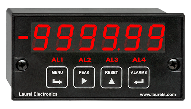
Dual relay outputs (two relays) or quad relay outputs (four relays) are available as an option in all Laureate 1/8 DIN digital panel meters, counters, timers, and serial input meters. Multiple alarm and control modes can be implemented by these relays around two programmable setpoints. The relays can be Form C contact relays or Form A solid state relays.
The Form C contact relays are SPDT and are rated 8A at 250 Vac or 24 Vdc. Contact relays are required to switch high currents.
The Form A solid state relays are SPST and are rated 120 mA at 140 Vac or 180 Vdc. Solid state relays are ideal for low switching currents and frequent operation.
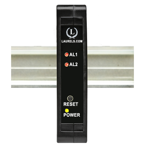
Dual solid state relays (two relays) are standard in Laureate 4-20 mA & RS485 DIN rail transmitters and 4-20 mA & Ethernet transmitters.
For additional relay information, please see our setpoint control page.
Applicable to a Wide Range of Instruments
Setpoint Operating Modes
- Operation above or below setpoint. Each relay may be individually programmed to be energized above or below a setpoint, or may be disabled.
- Latching or non-latching. Each relay may be individually programmed to operate in a latching or non-latching mode. In the latching mode, when an alarm or shutdown condition is reached, the output remains in the alarm condition until it is reset by front panel pushbuttons, via the serial interface, or via the rear connector. In the non-latching mode, the output is automatically reset when the alarm condition no longer exists.
- Band deviation mode. Each relay may be set to operate in a band deviation mode, where an alarm is generated whenever the reading is a specified number of counts above or below the setpoint. In particular, band deviation is ideal to flag an out-of-tolerance condition.
- Hysteresis mode. Each relay may be set to operate in a hysteresis mode, where turn-on occurs at a specified amount above the setpoint and turn-off occurs at the same amount below the setpoint.
- Filtered or unfiltered input. Relay action may be derived from either the filtered or unfiltered DPM input signals. Using the unfiltered signal improves response time, which is typically 17 ms for a DPM with the solid state relay board. Fast response time is one of the major strengths of Laureate DPMs, which can digitize analog data as often as 60 times per second. Using the filtered input reduces the chance of alarm triggering due to noise.
- Provisions for signal noise. A programmable time delay and reduction of relay chatter can be achieved in the DPM by selecting 1 to 128 readings in binary steps (20 ms to 2 s) prior to updating the output. Snubber circuitry is part of the contact relay board to prolong contact life. The relay response time of counters is controlled by a selectable gate time from 10 ms to 199.99 s.
- Additional setpoint control modes beyond those of normal meter or counter operation are provided by the Laureate Weight Meter and Batch Controller.
| Normal, Non-Latched Operation | |
|---|---|
 |
In this mode, the relay closes when the reading rises above the setpoint and opens when the reading falls below the setpoint. Relay ON/OFF control action is independently programmable for each of the two relays and can be reversed through a setup command. |
| Latched Operation | |
 |
The relay stays actuated until reset externally. This mode can be used to shut down machinery or a process when an operating limit has been exceeded, or to maintain an alarm until acknowledged by an operator when the alarm condition has passed. |
| Mixed Latched and Non-Latched Operation | |
 |
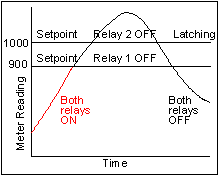
One of the relays can operate in a non-latched mode, for instance to turn off a heater when an operating temperature setpoint is reached. The other relay can operate as a latching fail-safe backup and turn off the entire process when a second, higher setpoint is reached, indicating a malfunction. |
| Deviation Mode Operation | |
 |
A deviation limit (50 in this example) is set up around both sides of the setpoint. The relay closes (or opens) when the reading falls within the deviation band, and opens (or closes) when the reading falls outside of this band. This mode sets up a passband around the setpoint and is often used for component testing. |
| Wide Hysteresis Mode Operation | |
 |
In this example, a hysteresis limit of 600 is set below the setpoint. The relay closes when the reading reaches a lower limit (the setpoint less hysteresis) and opens when the reading reaches an upper limit (the setpoint). One application is automatic tank filling. A fill operation is automatically initiated when the tank level has reached a lower level and is terminated when the level has reached an upper level. |
| Narrow Hysteresis Mode Operation | |
 |
Hysteresis can be used to minimize the number of ON/OFF control cycles around a setpoint, thereby increasing the life of motors, relays, etc. A very narrow hysteresis band (such as 5 counts) can also be used to minimize relay chatter around a setpoint due to electrical noise on the signal, or due to signal feedback caused by load switching. The hysteresis limit should exceed the noise amplitude. |
Electrical Connections

|

|
| Form C (SPDT) dual
contact relays Relays can be connected to be normally open (OC) or normally closed ($0). Relay grounds are mutually isolated. |
Form A (SPST) quad
contact relays Relays are normally open (NO). Each pair of relays shares an isolated ground. |

|

|
| Form A (SPST) dual solid
state relays Relays are normally open (NO). Relay grounds are mutually isolated. |
Form A (SPST) quad solid
state relays Relays are normally open (NO). Each pair of relays shares an isolated ground. |


