
Features
- Fits all Laureate 1/8 DIN size instruments
- Allows Laureate instruments to be polled using Modbus commands
- Network speeds of 10 or 100 Mbits/sec
- Can be polled via Ethernet every 2 msec
- Includes Mini-USB port for programming or data transfer at 38400 baud
- Isolated from meter and power grounds
Certificates of Compliance
LNET1 is a second generation communications board that plugs into the middle slot of a Laureate 1/8 DIN digital panel meter, counter or timer. It provides a high-speed Ethernet port to connect the host instrument to a local area network (LAN), plus a USB port for programming or data output to a PC or HMI. High data rates are a major advantage compared to Laurel's first-generation LNET communication boards. The LNET1 board is normally ordered by selecting "A" as the communication option of a configured instrument.
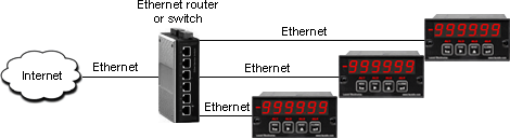
Ethernet operation complies with IEEE 802.3 and utilizes an industry-standard RJ45 jack for a 10/100 Base-T connection to a local area network (LAN) or directly to a PC or HMI. Data rates can be 10 or 100 Mbits/sec depending on the router. Using Ethernet and Modbus TCP, the LNET1 board can be polled every 2 msec. Multiple instruments, each with their own assigned IP address, can be individually addressed and polled.
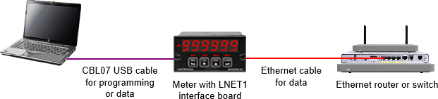
A mini-USB connector is standard and can be used for meter programming or for data polling as a Modbus slave at 38400 baud independently of polling via Ethernet. To connect to the USB port of a PC, use our cable CBL07 or another readily available A-male to Mini-B USB cable.
Cached operation is a key feature of the LNET1 board. It allows the host meter to be polled at the maximum rate allowed by the meter's main board, and in turn to be polled asynchronously at a much faster rate using external Ethernet or USB communications and Modbus RTU/TCP commands. These are documented in our LNET1 & LNET1-485 user manual. Updated analog readings can be retrieved every 17 or 20 msec, depending on the meter's 60 Hz or 50 Hz AC line noise rejection setting. Cashed counter readings can be retrieved every 10 msec.
Communications setup uses our free Laurel Network Setup (LNS) utility. That software automatically discovers the board's Ethernet IP address assigned by the WiFi router, the COM port used for USB communications, the meter type, and the signal conditioner type. It also allows the IP address to be assigned by the user. The USB port can be used with Laurel's free Instrument Setup (IS) software to set up all operating parameters of host instrument and remote instruments on an attached RS485 bus.
Networks with LNET1 Boards
 |
 |
| Ethernet Operation | |
|---|---|
| Ethernet application | Operation of host meter as a Modbus slave |
| Ethernet standard | IEEE 802.3 |
| Ethernet connector | RJ45 jack |
| Ethernet cable | 10/100 Base-T |
| Data rate | 10 or 100 Mbits/sec |
| Communications protocol | Modbus TCP (same commands as for Modbus RTU) |
| Min read interval from cache | 2 msec |
| USB Operation | |
| USB applications | Laurel Network Setup, host meter programming, operation of host meter as a Modbus slave. |
| USB connector | Mini-USB |
| USB cable | Mini-USB to Type A (CBL07) or customer furnished |
| Data rate | 38400 baud |
| Communications protocol | Modbus RTU (same commands as for Modbus TCP) |
| Min read interval from cache | 10 msec |
| COM port | Discovered by Laurel Network Setup (LNS) utility |
| Cache Memory | |
| Data written into cache | Display value or set of 6 values (user selectable) |
| 6 values for analog in DPMs | Alarm status, display value, peak, valley, display value, display value |
| 6 values for scale meters | Alarm status, display value, peak, net weight, gross weight, display value |
| 6 values for counters | Alarm status, item 1 (display value), peak, valley, item 2, item 3 |
| Write interval for 1 value | 18 msec or 21 msec (filtering set for 60 Hz or 50 Hz noise rejection) |
| Write interval for 6 values | 108 msec or 126 msec (filtering set for 60 Hz or 50 Hz noise rejection) |
| Read inteval from cache | Set by externa Modbus Master, 2 msec min for Ethernet, 10 msec min for USB |
| Measurement Update Intervals | |
| Analog input meter | 18 msec or 21 msec (filtering set for 60 Hz or 50 Hz noise rejection) |
| Totalized pulse readings | Signal period or programmable gate time from 10 msec to 199.99 sec |
| Frequency/rate readings | Gate time + 30 msec + 1-2 signal periods |
| Communication Protocols | |
| Meter polling via Ethernet | Modbus TCP (same command set as for Modbus RTU) |
| Meter polling via USB | Modbus RTU (same command set as for Modbus TCP) |
| Meter programming | Custom ASCII protocol for Instrument Setup (IS) software |
| Mechanical | |
| Board dimensions | 79 x 39 mm |
| Mounting location | Middle slot of Laureate Series 2 panel meter or counter |
| Environmental | |
| Operating temperature | -40°C to 85°C |
| Relative humidity | 95% from 0°C to 85°C, non-condensing |
| Electrical Protection | |
| Isolation | 250V rms working, 2.3 kV rms per 1 min test |
| ESD protection | 15 kV per IEC 1000-4-2 |
| EMI immunity | 10 V/m per IEC 1000-4-3 |
| EFT protection | 2 kV per IEC 1000-4-4 |
| Short circuit protection | Continuous |
