
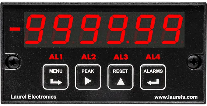
6-Digit Digital Stopwatch and Timer
Time Base Crystal calibrated to ±2 ppm Span tempco ±1 ppm/°C (typ)
Long-term Drift ±5 ppm/year (typ)
6-Digit Digital Stopwatch and Timer
Time Base Crystal calibrated to ±2 ppm Span tempco ±1 ppm/°C (typ)
Long-term Drift ±5 ppm/year (typ)
Time Interval of Periodic Events
Time Base Crystal calibrated to ±2 ppmSpan tempco ±1 ppm/°C (typ)
Long-term Drift ±5 ppm/year (typ)
Duty Cycle and (PWM)
Time Base Crystal calibrated to ±2 ppmSpan tempco ±1 ppm/°C (typ)
Long-term Drift ±5 ppm/year (typ)
Serial Input 6-Digit Remote Display
Display from -999,999 to +999,999
High read rates at up to 60 or 50 conversions per second.
An electronic timer is a panel-mounted digital instrument that measures durations and time-based events rather than a continuous signal value or a pulse count. Where a panel meter reads a voltage or temperature and a counter totalizes pulses, an electronic timer captures the time elapsed between two events — a single interval, an accumulated duration, a repeating cycle period, or the on/off ratio of a pulsed signal. These timers share Laurel's 1/8 DIN modular platform, with a 6-digit LED display, a time base crystal calibrated to ±2 ppm, and the same plug-in board architecture used across the meter and counter product lines, letting high-resolution timing sit on the same panel and use the same setup workflow as the rest of an instrument lineup.
A counter processes a pulse train — counting pulses or computing a rate from their frequency. A timer instead measures duration — the time elapsed between two events, whether that's a single interval, an accumulated total, or a repeating cycle period. Both share the same panel-mount platform, but a counter answers "how many" or "how fast," while a timer answers "how long."
Single event timing captures one interval from a start signal to a stop signal, similar to a stopwatch lap. Accumulated event timing instead sums the duration across multiple start/stop cycles into a running total, useful for tracking total run time across repeated on/off periods rather than just one interval.
Basic stopwatch timing captures a single, typically non-repeating interval. Periodic event timing is built specifically to measure the duration of a recurring cycle — the time between one occurrence of a repeating event and the next — which is useful for monitoring the rhythm or consistency of an ongoing process rather than a one-off measurement.
Duty cycle is the proportion of time a signal spends in its "on" state compared to the total cycle time, usually expressed as a percentage. A PWM-driven motor running at 70% duty cycle, for example, is receiving power for 70% of each switching cycle, which the timer calculates directly from the pulse's on-time and off-time.
It's a 6-digit display that receives its value over a serial connection (RS-232, RS-485, or Modbus) from another device, rather than measuring a signal itself. It functions as a large, clear remote readout for a value another instrument or controller has already computed, displaying anything from -999,999 to +999,999.
Resolution depends on the specific configuration, but single and accumulated event timing on these platforms can resolve intervals down to a fraction of a microsecond, which supports applications ranging from basic process timing to capturing very short, fast events.
Yes, with the appropriate option board. A timer can drive relay outputs from configurable time-based setpoints and retransmit its reading as an analog output, letting it serve as both an indicator and a simple time-based controller.
For many applications, yes — the high-resolution single and accumulated event timing functions are suited to capturing precise durations such as process dynamics or pulsed events, offering a panel-mounted, continuously logged alternative to a handheld stopwatch or a benchtop oscilloscope for that specific measurement task.
Confirming the start and stop trigger conditions (such as signal edge or logic level) are configured to match exactly what the connected sensor or switch actually outputs is the first step, since a mismatch between the expected and actual trigger condition can cause extra or missed start/stop events that accumulate into an incorrect total over time.
Some cycle-to-cycle variation is expected if the actual physical process isn't perfectly consistent, since the timer is accurately reporting real variation in event timing rather than introducing its own error; if the variation seems larger than the process itself should produce, checking for signal noise or a marginal trigger threshold on the input is the standard next step.
Confirming both instruments are measuring the same point in the circuit and using the same definition of "on" (such as active-high vs. active-low) is the first step, since a duty cycle calculation depends entirely on which signal transitions are being counted as the start and end of the "on" period.
Confirming the sending device is still actively transmitting on the expected serial protocol and address is the first step, since a remote display configuration shows whatever it last received and has no way to know the data source has stopped updating.
Confirming the setpoint value and relay mode (normally open vs. normally closed) are configured as intended is the first step, since a relay that appears not to trigger is often configured correctly but for a different condition than expected.
Confirming the exact start and stop trigger points match where the physical event actually begins and ends is the first step, since an event timer measures precisely between its configured triggers, and a trigger set slightly before the true start or after the true end will add that extra time into the reading even though the timer itself is functioning correctly.
Confirming whether a manual reset command was issued (through the front panel or a remote command) versus the total simply reaching its maximum display range and rolling over is the first step, since both will show a reset total but point to different causes and different fixes.
