
Features
- Two independently scalable totals for Channels A & B
- Arithmetic functions A+B, A-B, AxB, A/B, A/B-1 applied to rate or total
- Inputs from NPN or PNP proximity switches, contact closures, digital logic, magnetic pickups down to 12 mV, or AC inputs up to 250 Vac
- Frequencies from 0.005 Hz to 1 MHz
- Digital span adjustment: 0 to ±999,999; zero adjustment: -999,999 to +999,999
- Front panel scalable: 0 to ±999,999 for use with current shunts
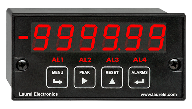
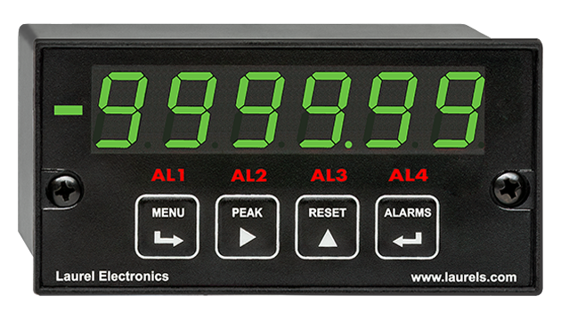
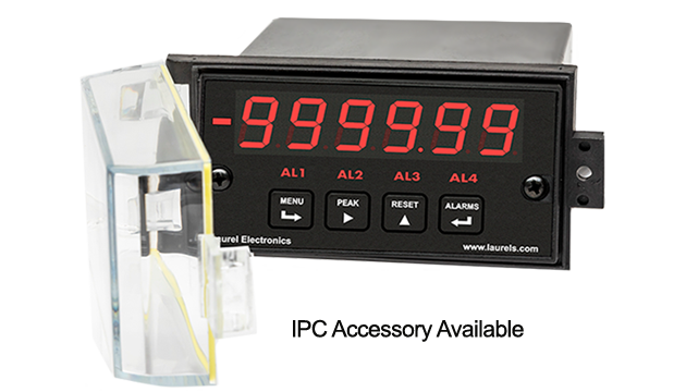
- 1/8 DIN size with bright red or green 0.56" (14.2mm), high LED digits
- Transducer excitation output, 5, 10, 12, or 24 Vdc (isolated)
- Power 85-264 Vac / 90-300 Vdc or 10-48 Vdc / 12-32 Vac (isolated)
- Operating temperature from -40°C to 70°C (-40°F to 158°F)
- Wide choice of Plug-in-Play options:
- 2 or 4 relays, mechanical or solid state, for alarm or control (isolated)
- 1 or 2 Analog output, 4-20 mA, 0-20 mA, 0-10V, or -10V to +10V (isolated)
- Communications: Ethernet, WiFi, USB, RS232, RS485 (isolated)
Certificates of Compliance
The Laureate™ 1/8 DIN Panel Meter for Arithmetic functions A+B, A-B, AxB, A/B, A/B-1
applied to channels A & B are a capability of Laureates with an Extended counter main board and FR dual-channel signal conditioner board that can display frequencies from 0.005 Hz to 1 MHz. These function are applicable to rate or total after scaling to engineering units. The following are application examples:- Add two flows (A+B) for total flow or total volume.
- Subtract two flows (A-B) for net flow or net volume.
- Take the ratio of two flow rates (A/B) for chemical mixing.
- Take the ratio of RPMs or belt speeds (A/B) to synchronize moving machinery.
- Subtract 1 from ratio (A/B-1) to control elongation of material compressed by rollers (draw).
Ratio and draw are similar, except that 1 is subtracted from ratio to obtain draw. The frequency of channels A or B is measured and converted to rate in engineering units by multiplying it by the appropriate scale factor for that channel. Either rate can be displayed. The A/B ratio is taken mathematically by the panel meter, and 1 is subtracted for draw. The result can be multiplied by a multiple or 10 from 0.00001 to 100000, and the decimal point can be set to display the result with the desired precision up to six digits.
The Laureate Panel Meter is easily programmed with Laurel’s free Instrument Setup Software, downloadable from our website and compatible with Windows PCs, requiring a data interface board for setup.
All signal conditioner board ranges are factory-calibrated, with calibration factors for each range securely stored in an onboard EEPROM. These factors can be scaled via software to accommodate external shunts, enabling field replacement of signal conditioner boards without necessitating recalibration of the associated panel meter. For optimal accuracy, factory recalibration is recommended annually. All Laurel Electronics instruments undergo factory calibration using the industry-leading Fluke calibrators, which are recalibrated yearly and certified traceable to national standards, ensuring the highest level of precision and reliability.
The Extended DPM Version Provides Capabilities Beyond Those of the Standard DPM Counter:
- Rate and total simultaneously. Channel A can display total while Channel B displays rate. The selection of A or B for display is via a front panel pushbutton. This mode is ideal for flow applications.
- Up/down counting. Channel A can serve as an up/down counter, where the count direction is dynamically changed by applying a signal to Channel B. For instance, Channel A can count and scale pulses from a turbine flow meter, while Channel B inputs the direction of flow. This allows total volume to be tracked in case of reversible flow.
- Totalizing with external inhibit. Totalizing by Channel A can be temporarily inhibited by applying a signal to Channel B. For instance, 60 Hz AC pulses can be counted by Channel A and be scaled to display elapsed hours. A signal can be applied to Channel B to start or stop pulse counting when a process is in operation.
- Custom curve linearization. Exceptionally accurate custom curve linearization is achievable, for example to linearize the low end of turbine flow meters. For setup, up to 180 data points can be input into a spreadsheet or text file by the user. The computer then calculates spline fit segments, which are downloaded into the panel meter via RS232. The linearized rate can then be totalized by the Extended counter.
- Arithmetic functions. The Extended counter makes arithmetic functions available, namely A+B, A-B, AxB, A/B and A/B-1. These solve many applications. For instance, A+B allows two input flows to be summed for total volume, while A-B allows outflow to be subtracted from inflow for net volume. A/B allows the mixing of ingredients in a specified ratio. By monitoring and alarming the A/B volume ratio, ingredient B can be added to A until the proper ratio is achieved.
Fast, High Resolution Measurement
Laureate counters determine frequency by timing an integral number of periods over a programmable gate time. The inverse period approach allows greater accuracy and faster update times than conventional meters which count signal pulses over a specified time interval. Channel A accepts pulses from 0.005 Hz to 1 MHz, while Channel B accepts pulses from 0.005 Hz to 250 kHz. At the minimum gate time of 10 ms, update rates can be up to 25/second. Such fast response is ideal for peak capture and for alarm and control applications. Variations in the displayed reading can be reduced by selecting a longer gate time. An adaptive digital filter can further reduce variations due to noise while rapidly responding to actual changes in the signal.
Digital signal filtering modes can be selected to ensure stable readings in electrically noisy environments.
- An unfiltered selection provides true peak and valley readings and aids in control applications.
- A batch average filter selection averages each 16 conversions.
- An adaptive moving average filter selection provides a choice of 8 time constants from 80 ms to 9.6 seconds. When a significant change in signal level occurs, the filter adapts by briefly switching to the shortest time to follow the change, then reverts back to its selected time constant. An Auto setting selects the time constant selection based on signal noise.
Peak and valley values are automatically captured. These may be displayed via a front panel pushbutton command or control signal at the rear connector, or be transmitted as serial data.
Two rear panel control Inputs (CMOS/TTL levels, logic 0 = tied to digital ground, logic 1 = open) or dry contacts that can be set to control / activate 14 meter commands.
An (isolated) 5, 10, 12, or 24 Vdc excitation output is standard to power transducers or two-wire transmitters. Ratiometric operation, which automatically compensates for changes in the applied excitation, is jumper selectable for applications, such as bridges, where the signal to be measured is proportional to the excitation level.
Universal Signal Conditioner
The Laureate dual-channel signal conditioner accepts inputs from proximity switches with PNP or NPN output, TTL or CMOS logic, magnetic pickups, contact closures, low-level outputs from turbine flow meters down to 12 mV, or high-level AC line inputs to 250 Vac. Jumper selections provide optimum operation for different sensor types and noise conditions. A built-in (isolated) 5, 10, 12, or 24 Vdc excitation supply can power proximity switches or other sensors, and eliminate the need for an external power supply.
| Display | |
|---|---|
| Readout | 6 LED digits, 7-segment, 14.2 mm (.56"), red or green. |
| Display Range | -999,999 to +999,999, XXXXEX notation beyond 999,999 |
| Zero Adjust | -999,999 to +999,999 |
| Span Adjust | 0 to ±999,999 |
| Indicators | Four LED lamps |
| Inputs | |
| Types | AC, pulses from NPN, PNP transistors, contact closures, magnetic pickups. |
| Signal Ground | Common ground for channels A & B |
| Channel A Freq. | 0.005 Hz to 1 MHz |
| Channel B Freq. | 0.005 Hz to 250 kHz |
| Minimum Signal | Nine ranges from (-12 to +12 mV) to (+1.25 to +2.1V). |
| Maximum Signal | 250 Vac |
| Noise Filter | 1 MHz, 30 kHz, 250 Hz (selectable) |
| Contact Debounce | 0, 3, 50 ms (selectable) |
| Recalibration: All ranges are calibrated at the factory. Recalibration is recommended every 12 months. | |
| Rate Accuracy | |
| Time Base | Crystal calibrated to ±2 ppm |
| Span tempco | ± 1 ppm/°C (typ) |
| Long-term Drift | ± 5 ppm/year |
| Power Supply Boards (one required) | |
| Voltage, standard | 85-264 Vac or 90-300 Vdc |
| Voltage, optional | 12-32 Vac or 10-48 Vdc |
| Frequency | DC or 47-63 Hz |
| Power consumption (typical, base meter) | 1.2W @ 120 Vac, 1.5W @ 240 Vac, 1.3W @ 10 Vdc, 1.4W @ 20 Vdc, 1.55W @ 30 Vdc, 1.8W @ 40 Vdc, 2.15W @ 48 Vdc |
| Power Isolation | 250V rms working, 2.3 kV rms per 1 min test |
| Excitation Output (standard) | |
| 5 Vdc | 5 Vdc ± 5%, 100 mA (jumper selectable) |
| 10 Vdc | 10 Vdc ± 5%, 120 mA (jumper selectable) |
| 12 Vdc | 12 Vdc ± 5%, 100 mA (jumper selectable) |
| 24 Vdc | 24 Vdc ± 5%, 50 mA (jumper selectable) |
| Output Isolation | 50 Vdc from signal ground |
| Analog Output Boards (one optional) | |
| Output levels | 4-20 mA, 0-20 mA, 0-10V, -10 to +10V (single-output option) |
| 4-20 mA, 0-20 mA, 0-10V (dual-output option) | |
| Current compliance | 2 mA at 10V ( > 5 kΩ load) |
| Voltage compliance | 12V at 20 mA (< 600 Ω load) |
| Scaling | Zero and full scale adjustable from -99999 to +99999 |
| Resolution | 16 bits (0.0015% of full scale) |
| Isolation | 250V rms working, 2.3 kV rms per 1 min test |
| (dual analog outputs share the same ground) | |
| Relay Output Boards (one optional) | |
| Dual magnetic relays | 2 Form C, 10A max, 440Vac or 125Vdc max, 2500VA or 300W |
| Quad magnetic relays | 4 Form A (NO), 10A max, 440Vac or 125Vdc max, 2500VA or 300W |
| Dual solid state relays | 2 Form A (NO), AC or DC, 0V - 400V, 120Ma, 35Ohms (max at On-State) |
| Quad solid state relays | 4 Form A (NO), AC or DC, 0V - 400V, 120Ma, 35Ohms (max at On-State) |
| Relay commons | Isolated commons for dual relays or each pair of quad relays |
| Relay isolation | 250V rms working, 2.3 kV rms per 1 minute test |
| Relay latching modes | Latching or non-latching |
| Relay active modes | Active on or off, active high or low |
| Hysteresis modes | QA passband mode, split hysteresis, span hysteresis |
| Communication Boards (one optional) | |
| Board selections | RS232, RS485 with dual RJ11 connectors, RS485 with dual RJ45 connectors, USB, Ethernet, USB-to-RS485 gateway, Ethernet-to-RS485 gateway, WiFi with built-in antenna plus USB & RS485, WiFi with external antenna plus USB & RS485 |
| Protocols | Laurel Custom ASCII (serial), Modbus RTU (serial), Modbus TCP (Ethernet or WiFi) |
| Digital addresses | 247 (Modbus), 31 (Laurel ASCII), |
| Isolation | 250V rms working, 2.3 kV rms per 1 min test |
| Environmental | |
| Operating temperature | -40°C to 70°C (-40°F to 158°F) |
| Storage temperature. | -40°C to 85°C (-40°F to 185°F) |
| Relative humidity | 95% at 40°C, non-condensing |
| Protection | NEMA-4X (IP-65) when panel mounted |
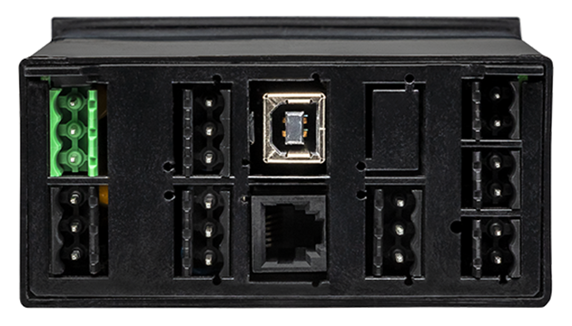
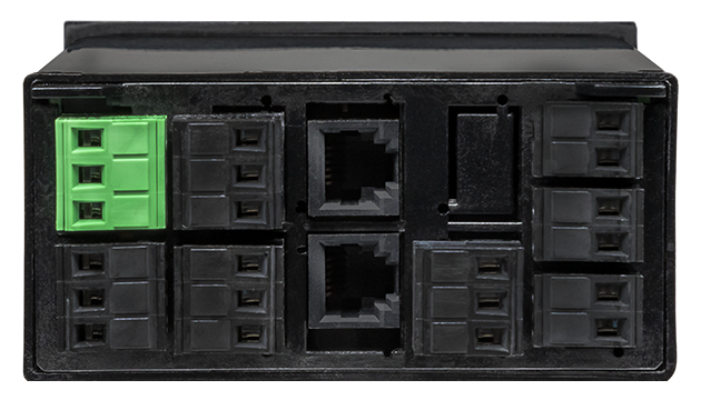
| Electrical Connections | |
 |
|
| Mechanical | |
| Enclosure | 1/8 DIN, high impact plastic, UL 94V-0, color: black |
| Mounting | 1/8 DIN panel cutout required: 3.622" x 1.772" (92 mm x 45 mm). |
| Dimensions | 4.68" x 2.45" x 5.64" (119 mm x 62 mm x 143 mm) (W x H x D) |
| Maximum panel thickness | 4.5 mm (0.18") |
| Tightening Torque - Connectors | Screw terminal connectors: 5 lb-in (0.56 Nm) |
| Tightening Torque - Pawls | Digital Panel Meter Case Pawls: 5 lb-in (0.56 Nm) |
| Weight of base meter | 210 g (7.4 oz) typical (DPM, counter, timer, 6-digit remote display) |
| Weight of option boards | 30 g (1.0 oz) typical per board (analog output, relay output, communications) |
| General | |
| Programming Methods | Four front panel buttons or via Laurel's free Instrument Setup Software, which runs on a PC under MS Windows. |
| Security | Lockout options include using the front panel buttons, the free Instrument Setup Software, or a hardware jumper. |
| Warranty | 3 years parts & labor |
| Recalibration: All ranges are calibrated at the factory. Recalibration is recommended every 12 months. | |
Free Instrument Setup Software for Series 2 Laureates
|
|
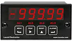
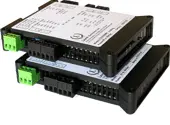
| 1/8 DIN Digital Panel Meters | DIN Rail Transmitters |
Free Downloadable Windows-based Instrument Setup (IS) software (Data Interface Board Required) for use with our programmable Digital Panel Meters, Scale Meters, Counters, Timers, Remote Displays, and Transmitters, are an easy method to set up Laureate 1/8 DIN digital panel meters, counters, timers, remote displays, and DIN-rail transmitters, as explained in the Instrument Setup Software Manual. Laureate 1/8 DIN instruments can also be set up from the front panel, as explained in their respective Owners Manuals. Instrument Setup software is of benefit whether or not the PC is connected to the instrument.
- When the PC is connected to the instrument, Instrument Setup software can retrieve the setup file from the instrument or open a default setup file or previously saved setup file from disk View Setup, then provides graphical user interface (GUI) screens with pull-down menus applicable to input, display, scaling, filtering, alarms, communications, analog output, and front panel lockouts. Fields that are not applicable to the instrument as configured are either left out or grayed out. Clicking on any item will bring up a detailed Help screen for that item. After editing, the setup file can be downloaded, uploaded to the instrument, or saved to a disk. The same setup file can then be downloaded into multiple instruments.
- When the PC is not connected to the instrument, the above GUI screens can be used to set up a virtual instrument. The setup file can then be saved to disk. Switching toView Menu then brings up a screen with the required front panel programming steps. This view can be printed out for use at the instrument site and to serve as a hard copy record.
Download Free Instrument Setup Software
Installation
Set User Account Control (UAC) of MS Windows to "Never notifiy me" so that Instrument Setup Software can create directories. The UAC change screen can be reached as follows:
- Under Windows 7, click on the Windows Start button in the lower left of the desktop and enter "UAC" in the search field.
- Under Windows 8, navigate to Control Panel, then to the "User Accounts and Family Safety" section, and click on "Change User Account Control Settings."
- Under Windows 10, click on the Windows Start button in the lower left of the desktop, then on "Settings", and enter "UAC" in the search field.
- Reboot your computer for the changed UAC setting to take effect.
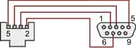
RJ11-to-DB9 cable with rear view of DB9 connector to PC
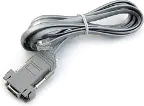
RS232 cable, meter to PC, P/N CBL01
Laureate 1/8 DIN Laureate instruments must be equipped with a serial communications board and be connected to the computer via a serial communications cable. The connection can be via RS232, RS485, USB or Ethernet. Following setup, the serial communications board may be removed from the instrument if desired. The wiring of the RS232 cable is illustrated above with end views of the two connectors.
Laureate LT Series transmitters come standard with a 3-wire serial interface, which can be jumpered for RS232 or RS485.
Laureate LTE Series transmitters come standard with an Ethernet interface.
Meter Setup Screens
Click on any of the reduced screens below for a full-size screen view, then click on the Back button of your browser to return to this page. The screens examples below are for a fully-loaded Series 2 Digital Panel Meter (DPM), which is connected to the PC via RS232. If the meter is a Series 1 meter (pre-2007), this is sensed by the software, and somewhat different screens are brought up. Please see Series 1 setup screens.

Welcome Screen
From the computer desktop, click on Start > Programs > IS2 > IS2. Or click on the IS icon on your desktop. This splash screen will be displayed for three seconds. The software revision number is in the lower right.


Communications Selection Screen
Specify your desired communication protocol and the serial communications bus type, which should match the jumper setup of the instrument. Select None if the PC is not connected to the instrument.

Establish Communications Screen
If you selected RS-232, you will be asked to specify the PC Com Port and Baud Rate, which should match the jumper setup of the instrument. Click on Establish. With the right settings, the Communications Established field will light up in green, and the Meter Type will be recognized. If so, click onMain Menu.

Main Menu Screen
Click on File > Default Setup to retrieve the default setup file from disk for your type of meter. Click on File > Open Setupto retrieve a previously saved setup file from disk or on File > Save Setup to save your edited setup file to disk. Click onDPM > Get Setup to retrieve the setup file from your meter or on DPM > Put Setup to download your edited setup file into the meter.

DPM Input + Display Setup Screen
From the Main Menu, click on View > Setup, then on theInput+Display tab. You can now specify the meter hardware, signal type, display mode, and functions of control inputs A and B. Clicking on any item brings up a pull-down menu with the available choices.

DPM Scaling Setup Screen
Click on the Scaling tab, which provides three scaling methods to relate the signal to the displayed reading: 1) Scale and Offset method, 2) Coordinates of two points method, and 3) Reading Coordinates of Two Points method. The last method uses actual high and low signals, and the computer will prompt you.

DPM Filter Setup Screen
Click on the Filter tab, which allows you to specify the digital filter time constant (if any), the adaptive filter threshold, and whether Peak / Valley values are filtered or unfiltered. As for all setup screens, clicking on the F1 key while an item is highlighted brings up a Help screen for that item, as illustrated.

DPM Relay Alarms Setup Screen
Click on the Relay Alarms tab, which allows you to set up Alarms 1 and 2 for the optional dual relay output board. Clicking on any of the four numeric fields changes these to green and brings up a special field to enter the desired numeric value, which is tied to the displayed reading.

DPM Communications Setup Screen
Click on the Communications tab so set up serial communications. In particular, you can special the Serial Protocol and the meter address if multiple meters are to be addressed on the same serial data line.

DPM Analog Output Setup Screen
Click on the Analog Out tab so set up the optional analog output board. Three output ranges are selectable, the endpoints of which can be tied to user-specified High and Low readings.

DPM Lockouts Setup Screen
Click on the Lockouts tab to check off menu items which will no longer be accessible from the front panel of the meter. This will simplify meter operation and prevent unintended setup changes.
Meter Setup Utilities

DPM Front Panel Setup Screen
As an aid to programming the meter from the front panel when a serial connection is not available, you can return to the Main Menu and click on View > Menu. The required sequence of front panel screens will then be displayed. Click on any step in the sequence for the meaning of each digit, as illustrated for the FILtEr step. For a hardcopy, simply press on Print.

DPM Jumper Setup Screen
Specify your desired communication protocol and the serial communications bus type, which should match the jumper setup of the instrument. Select None if the PC is not connected to the instrument.

DPM Jumper Setup Screens
Click on any of the displayed plug-in boards, and you will be presented with the jumper positions and electrical connections for your selected board. This minimizes the need to refer to the printed manual.

DPM Commands Screen
This page allows you set up external input, serial communications, an analog output proportional to the display (optional), and lockouts for Laureate digital counters. The grayed out area at the top right of the screen applies to Laureate remote displays.


Graphical Output Screens (not available with Ethernet)
From the Main Menu, click on Readings if your PC is connected to the meter. A pull-down menu then offers three choices: List, Plot and Graph.
- List presents the latest readings in a 20-row by 10-column table. Press Pause at any time to freeze the display. This is one method to capture peak readings.
- Plot generates a plot of readings vs. time in seconds. It effectively turns the DPM-PC combination into a printing digital oscilloscope.
- Graph generates a histogram where the horizontal axis is the reading and the vertical axis is the number of occurrences of readings. The display continually resizes itself as the number of readings increases.

DPM Calibration Screens
Click on the Scaling tab, which provides three scalClick on the Scaling tab, which provides three scaling methods to relate the signal to the displayed reading: 1) Scale and Offset method, 2) Coordinates of two points method, and 3) Reading Coordinates of Two Points method. The last method uses actual high and low signals, and the computer will prompt you.

Frequency Meter Calibration Screen
Calibration of the quartz crystal of the Laureate frequency meter requires the input of a known frequency from a calibrator. Apply the frequency, then enter the frequency in Hertz. Calibration will be automatic, with storage of the calibration factor stored in non-volatile memory.
Laureate™ 1/8 DIN Case For Laureate Digital Panel Meters, Counters, Timers & Remote Displays
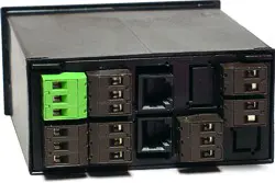
Key Features
- Meets 1/8 DIN Standard.
- Installs from front of panel.
- Short depth behind the panel: only 4" (102 mm) plus connectors.
- Understated 0.157" (4 mm) thick bezel.
- Meets NEMA 4X (IP-65) for high-pressure wawshdon when panel mounted.
- Screw clamps connectors meet VDE / IEC / UL / CSA safety standards.
- Rugged GE Lexan® housing material.
- Safety certified per EN 61010-1.


Dimensions
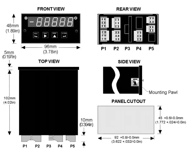
Maximum panel thickness: 4.5 mm (0.18")
Weight of base meter: 210 g (7.4 oz) typical (DPM, counter, timer, 6-digit remote display)
Weight of option boards: 30 g (1.0 oz) typical per board (analog output, relay output, communications)
Tightening Torque - Connectors: Screw terminal connectors: 5 lb-in (0.56 Nm)
Tightening Torque - Pawls: Digital Panel Meter Case Pawls: 5 lb-in (0.56 Nm)
Dimensioned CAD assembly drawings in EPRT, STEP, x_t. dwg, pdf file formats: Laureate-meter-case.zip (zipping prevents browser from opening CAD files as text files).
Panel Mounting
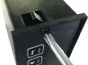 Slide the meter into a 45 x 92 mm 1/8 DIN panel cutout. Ensure that the provided gasket is in place between the front of the panel and the back of the meter bezel.
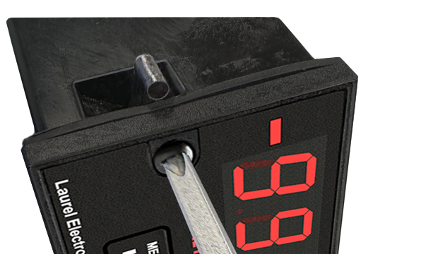
The meter is secured by two pawls, each held by a screw, as illustrated. Turning each screw counterclockwise extends the pawl outward from the case and behind the panel. Turning each screw clockwise further tightens it against the panel to secure the meter.
Slide the meter into a 45 x 92 mm 1/8 DIN panel cutout. Ensure that the provided gasket is in place between the front of the panel and the back of the meter bezel.
The meter is secured by two pawls, each held by a screw, as illustrated. Turning each screw counterclockwise extends the pawl outward from the case and behind the panel. Turning each screw clockwise further tightens it against the panel to secure the meter.
Turning each screw counterclockwise loosens the pawl and retracts it into its well. This position allows installed meter to be removed from their panel, or new meters to be installed in a panel. Do not remove the screws from their pawls. Doing so would cause the screw and pawl to fall off and likely get lost. Do not overtighten so as not to damage the plastic parts.


| Controlling the Mixing Ratio of Two Fluids | |
|---|---|
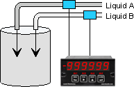 |
Displaying and alarming the input flow rate ratio of two fluids (gas or liquid) allows these to be mixed in a predetermined ratio in continuous processes. The sensing element is normally a turbine flowmeter, which outputs pulses at a frequency proportional to flow rate. The A/B ratio can also be displayed for totalized rate (or delivered volume). |
| Computing Net Fluid Inflow & Outflow | |
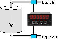 |
The ratio of the inflow and outflow rates of a tank is a measure of the relative filling or emptying rate. The same meter can also be programmed to display the net inflow or outflow rate in flow units, or to display totalized inflow our outflow in volume units. Any of these parameters can be alarmed using the dual relay board and be transmitted via 4-20 mA, RS232 or RS485. |
| Controlling Coating Thickness on a Film | |
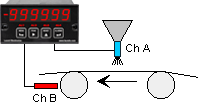 |
In this application, Channel A measures the rate at which a coating material is applied, as measured by a flow meter, while Channel B measures the speed of the film based on pulses from a proximity switch. Displaying and alarming the A/B ratio assures that an even thickness of coating material is applied as the speed of the film is varies. |
| Synchronizing Two Conveyor Lines | |
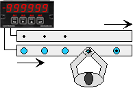 |
The dual-channel Laureate counter can measure the speed of conveyor lines by using the output of proximity switches which sense gear teeth or spokes of rotating drive wheels. Displaying the speed ratio of two lines allows line speeds to be adjusted so that material arrives at work stations when needed. |
| Measuring Draw for Elongation | |
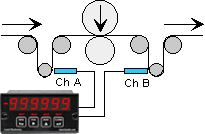 |
Draw (Ch A / Ch B - 1) can be used to display the elongation of films compressed between rollers, the shrinkage films, and the RPM difference of rollers whose speed is varied to maintain tension. The six-digit resolution of the Laureate dual channel counter / rate meter is ideal for comparison of rates that are close to each other. |
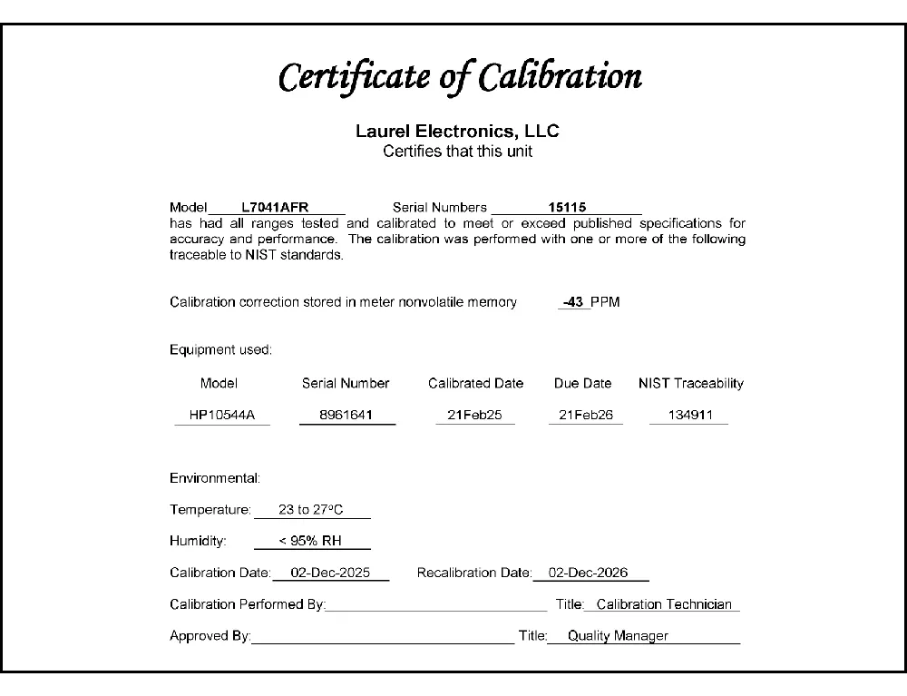
CAL-Digital
Certificate of Calibration
$65.00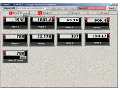
DLS-XLOG2
XLog2 Data logging Software
$495.00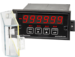
IPC
Digital Panel Meter Splashproof Cover
$55.00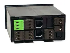

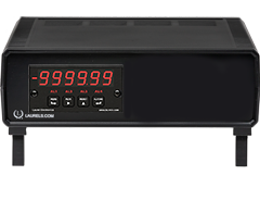
CASE1
Digital Panel Meter Benchtop Case1
$150.00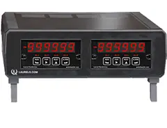
CASE2
Digital Panel Meter Benchtop Case2
$150.00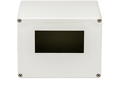
BOX1
DPM Enclosure Nema-4x Box1
$180.00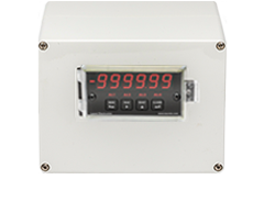
BOX2
DPM Enclosure Nema-4x BOX2
$230.00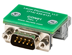
CON01
CON01 Connector
$75.00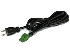
CBL6
6-foot Power Cable
$41.00CBL12
12-foot Power Cable
$47.00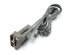
CBL01
RS232 Cable for Meters
$35.00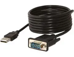
CBL02
USB-to-RS232 Adapter Cable
$47.00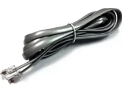
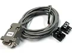
CBL04
RS232 Cable for LT Transmitters
$47.00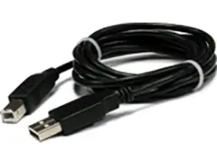
CBL05
USB Data Cable for Meters
$47.00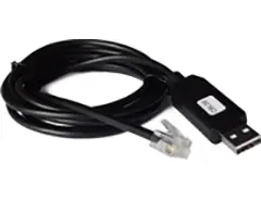
CBL06
USB-to-RS485 Adapter Cable
$47.00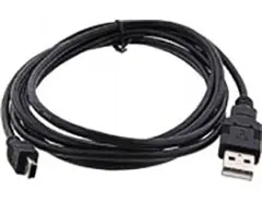
CBL07
USB Programming & Data Cable
$47.00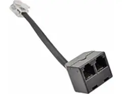
CBL08
RS485 Splitter Cable
$33.00Modular Design for Maximum Flexibility at Minimum Cost
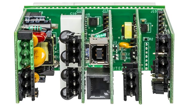
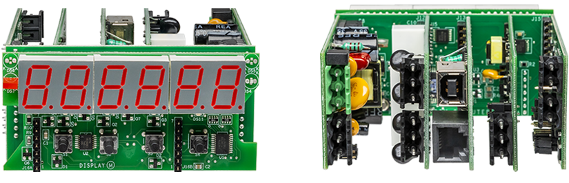
All boards are isolated from meter and power grounds. Optional Plug-in-Play boards for communications and control include Ethernet, WiFi, serial communication boards, dual or quad relay boards, and an analog output board. Laureates may be powered from 85-264 Vac or optionally from 12-32 Vac or 10-48 Vdc. The display is available with bright red or green 0.56" (14.2mm) high LED digits. The 1/8 DIN case meets NEMA 4X (IP65) specifications from the front when panel mounted. Any setup functions and front panel keys can be locked out for simplified usage and security. A built-in 5, 10, 12, or 24 Vdc excitation supply can power transducers, eliminating the need for an external power supply. All power and signal connections are via UL / VDE / CSA rated screw clamp plugs.
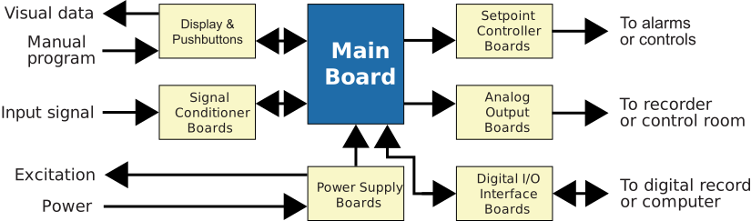
The Laureate™ Series features modular design with up to 7 isolated plug-in boards, applicable to all Laureate 1/8 DIN Panel Meter.
Modular Hardware
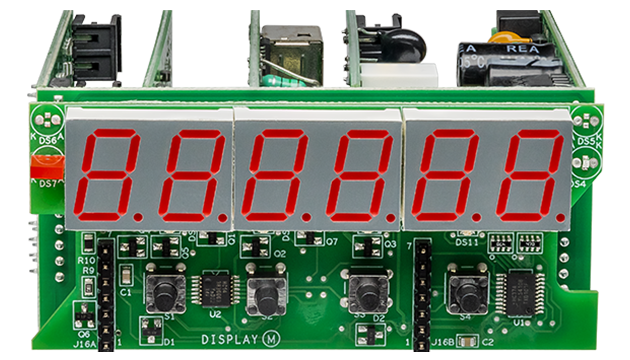
The design of the Laureate™ Series is modular for maximum flexibility at minimum cost. All boards are isolated from meter and power grounds. The base configuration for a panel meter or counter consists of a main module (with computer and plug-in display boards), a power supply board, and a signal conditioner board. Optional plug-in-play boards include an isolated setpoint controller board, an isolated analog output board, and an isolated digital interface board. Modular design and a choice of plug-in options allow the Laureate to be customized for a broad range of applications from simple monitoring to control and computer interface. There can be up to five plug-in boards in a 1/8 DIN Laureate.
Connecting Laureate Panel Meter to a Local Area Network (LAN)
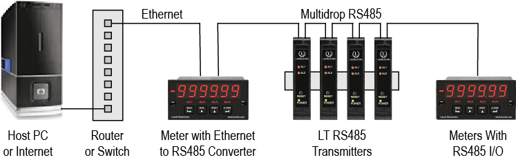
Up to 30 Laureate Panel Meter and/or LT Transmitters can be configured for RS485 and daisy-chained to an LT Transmitter using Laurel’s High Speed Ethernet-to-RS485 converter board for seamless LAN integration. Alternatively, Laurel LTE series Ethernet transmitters can connect directly to a LAN via an Ethernet cable. Setup for both configurations is streamlined using Laurel’s free Instrument Setup Software, which simplifies node discovery and transmitter configuration.
Flexible Communication Options for Panel Meter
The Laureate Panel Meter can be equipped with Laurel communication boards to support various interfaces and protocols. These include serial interfaces with ASCII or Modbus RTU protocols, and Ethernet interfaces with web access, ASCII, or Modbus TCP/IP protocols, ensuring versatile connectivity for your commercial applications.
Understanding the Laureate™ 1/8 DIN Panel Meter for Rate, Totalizer, and Functions A+B, A-B, AxB, A/B, A/B-1
Arithmetic functions A+B, A-B, AxB, A/B, and A/B-1 applied to Channels A and B are a capability of Laureate counters equipped with the Extended counter main board and the FR dual-channel signal conditioner board, which can measure frequencies from 0.005 Hz to 1 MHz. These functions apply to rate or total after scaling to engineering units.
Ratio and Draw
Ratio and draw are closely related: draw is simply the ratio with 1 subtracted (A/B-1). The frequency of Channel A or B is measured and converted to rate in engineering units by multiplying it by the appropriate scale factor for that channel, and either rate can be displayed. The meter takes the A/B ratio mathematically, subtracting 1 for draw. The result can be multiplied by a power of 10 from 0.00001 to 100000, with the decimal point set to display the result at the desired precision, up to six digits.
Application Examples
- Add two flows (A+B) for total flow or total volume.
- Subtract two flows (A-B) for net flow or net volume.
- Take the ratio of two flow rates (A/B) for chemical mixing.
- Take the ratio of RPMs or belt speeds (A/B) to synchronize moving machinery.
- Subtract 1 from ratio (A/B-1, draw) to control elongation of material compressed by rollers.
Real-World Applications
- Controlling the Mixing Ratio of Two Fluids — displaying and alarming the input flow rate ratio of two gases or liquids allows them to be mixed in a predetermined ratio in continuous processes. The sensing element is typically a turbine flow meter outputting pulses at a frequency proportional to flow rate; the A/B ratio can also be applied to totalized rate or delivered volume.
- Computing Net Fluid Inflow and Outflow — the ratio of a tank's inflow and outflow rates measures the relative filling or emptying rate. The same meter can be programmed to display net inflow/outflow rate in flow units, or totalized inflow/outflow in volume units, with any parameter alarmed via the dual relay board and transmitted via 4-20 mA, RS232, or RS485.
- Controlling Coating Thickness on a Film — Channel A measures the rate at which coating material is applied (via a flow meter), while Channel B measures film speed (via proximity switch pulses). Displaying and alarming the A/B ratio ensures even coating thickness as film speed varies.
- Synchronizing Two Conveyor Lines — the meter measures conveyor speed using proximity switches sensing gear teeth or drive wheel spokes on each line. Displaying the speed ratio of the two lines allows adjustment so material arrives at work stations when needed.
- Measuring Draw for Elongation — draw (Channel A / Channel B - 1) displays the elongation of film compressed between rollers, shrinkage of film, or the RPM difference of rollers whose speed is varied to maintain tension. The meter's six-digit resolution suits comparison of rates that are close to each other.
Extended Counter Capabilities
Beyond the arithmetic functions, the Extended counter version adds: rate and total displayed simultaneously (Channel A total, Channel B rate, toggled via front-panel pushbutton); up/down counting (Channel A counts while Channel B sets direction, tracking total volume correctly even with reversible flow); totalizing with external inhibit (a Channel B signal starts or stops Channel A's totalizing); and custom curve linearization (up to 180 user-entered data points, spline-fit and downloaded to the meter, useful for linearizing the low end of turbine flow meters).
Fast, High-Resolution Measurement
The meter determines frequency by timing an integral number of periods over a programmable gate time, then taking the inverse — this inverse-period approach gives greater accuracy and faster update times than conventional pulse-counting meters. Channel A accepts 0.005 Hz to 1 MHz; Channel B accepts 0.005 Hz to 250 kHz. At the minimum 10 ms gate time, update rates reach up to 25 per second, well suited to peak capture and alarm/control applications.
Factory-Calibrated Accuracy
All signal conditioner board ranges are factory-calibrated, with calibration factors stored in an onboard EEPROM that can be scaled via software to accommodate external shunts — enabling field replacement of the signal conditioner board without recalibrating the meter. The internal time base is crystal-calibrated to ±2 ppm, with span tempco of ±1 ppm/°C and long-term drift of ±5 ppm/year. Factory recalibration is recommended annually.
Rate, Totalizer & Ratio Panel Meter Frequently Asked Questions
What is the difference between ratio (A/B) and draw (A/B-1)?
Ratio is simply Channel A's rate divided by Channel B's rate. Draw subtracts 1 from that ratio, which is useful specifically for elongation or shrinkage applications where a ratio of exactly 1.0 (no stretch) should display as zero rather than as 1.0.
Why would I use A/B ratio instead of just comparing two separate rate displays manually?
Manually comparing two separately displayed rates requires an operator to do the math and notice a deviation, whereas the meter calculating and directly alarming the A/B ratio catches an out-of-tolerance condition automatically and immediately — critical in applications like chemical mixing or film coating where a delayed manual catch could waste material or produce an out-of-spec product.
Can the ratio or draw result be scaled to a specific precision or multiplied by a factor?
Yes. The A/B or A/B-1 result can be multiplied by a power of 10 ranging from 0.00001 to 100000, with the decimal point set to display the result at the desired precision, up to six digits — useful for expressing a ratio close to 1.0 (as in draw applications) with meaningful resolution.
Can this meter sum two flows for a total, and separately calculate their ratio, at the same time?
The function applied to Channels A and B (A+B, A-B, AxB, A/B, or A/B-1) is a single selected math mode rather than several running in parallel — so summing (A+B) and calculating ratio (A/B) would require selecting one function at a time rather than displaying both simultaneously from the same configuration.
What sensor types are compatible with the two input channels for a ratio application?
The FR signal conditioner accepts NPN or PNP proximity switches, TTL/CMOS logic, magnetic pickups, contact closures, low-level turbine flow meter outputs down to 12 mV, and AC line inputs up to 250 Vac — so a ratio application can compare, for example, two turbine flow meters, two proximity-switch speed sensors, or a mix of sensor types across the two channels.
Does the meter need external power to run the proximity switches or sensors feeding Channels A and B?
Not necessarily. A built-in isolated excitation supply (5, 10, 12, or 24 Vdc, jumper-selectable) can power both sensors directly, eliminating the need for separate external power supplies.
How is the ratio or draw alarm typically used in a coating thickness or draw control application?
With the relay output option, the A/B or A/B-1 result can trigger an alarm when the ratio drifts outside an acceptable band — for example, flagging when coating thickness (via the flow-to-film-speed ratio) or film elongation (via the draw calculation) moves out of tolerance, so an operator or automated control loop can correct it before significant off-spec material is produced.
Can the ratio or total be transmitted to a PLC or SCADA system rather than only displayed locally?
Yes. The calculated ratio, draw, sum, difference, or total can be transmitted via RS232, RS485 (Modbus RTU), Ethernet (Modbus TCP), or an isolated 4-20 mA/0-10V analog output, in addition to the local front-panel display.
How accurate is the ratio calculation itself, separate from the sensors feeding it?
The meter's internal time base is crystal-calibrated to ±2 ppm with long-term drift of only ±5 ppm/year, so the ratio math itself introduces negligible error — the practical accuracy of a ratio application depends far more on the accuracy and matching of the two sensors and flow meters feeding Channels A and B than on the meter's own calculation.
Is a separate meter needed for each math function, or can the same meter be reconfigured between A+B, A-B, AxB, A/B, and A/B-1 later?
The same physical meter can be reconfigured between these functions in the field via the front panel or Instrument Setup Software, since they're all software-selected modes of the same Extended counter hardware rather than separate physical configurations — so a meter set up for A+B summing today can be reconfigured for A/B ratio later without needing different hardware.
Rate, Totalizer & Ratio Panel Meter Questions From the Field
Why does my A/B ratio reading spike to an implausible value occasionally, even though both flows look steady?
This is commonly caused by one channel briefly dropping to zero or a very low value — since A/B is a division, even a momentary near-zero reading on the B channel (from a signal dropout, slow startup, or noise) can produce a momentary, wildly large or erratic ratio result. Checking whether the spike coincides with a brief signal interruption on either channel, rather than assuming a persistent calibration issue, usually explains it.
My coating thickness ratio (A/B) is correct most of the time but drifts during startup or line speed changes — why?
Transient mismatches between the two channels' response times are a frequently reported cause — if one sensor or flow meter responds faster to a speed change than the other, the ratio can briefly show an incorrect value during acceleration or deceleration even though both channels settle to correct readings once speed stabilizes. Reviewing whether ratio alarms are specifically occurring during speed transitions, rather than during steady-state operation, helps distinguish this from a genuine sensor problem.
Why does my draw (A/B-1) reading show a small nonzero value even when I believe the film isn't stretching at all?
A small residual nonzero draw reading at a supposedly 1:1 ratio is commonly explained by minor mismatch in scale factors between the two channels, or genuine small mechanical differences between rollers (such as slightly different diameters) rather than an actual process issue. Verifying both channels' scale factors are correctly matched to their actual pulses-per-revolution, and confirming roller diameters against the assumed values used in scaling, resolves most of these small residual offsets.
Why does my A/B ratio alarm trigger falsely when both individual flow rates still look reasonable on their own?
This is often traced to the deviation limit around the target ratio being set too tight relative to normal process variation, since even small, individually-acceptable fluctuations in each flow can combine into a ratio deviation that crosses a narrow alarm threshold. Reviewing the alarm deviation band against actual observed ratio variation during known-good operation, rather than assuming both flows must be individually out of range to trigger a ratio alarm, clarifies this.
Can noise on one channel affect a ratio calculation more than it would affect that channel's rate reading alone?
Yes — because ratio calculations amplify small errors through division, noise-driven jitter on either input channel can produce a proportionally larger effect on the calculated ratio than it would on that channel's rate display alone, particularly when the two channels' rates are close to each other (as in draw applications). Applying the adaptive digital filter or a longer gate time on both channels is generally more important for ratio and draw applications than for simple rate display.
Why does my conveyor line synchronization ratio work fine at full speed but become unreliable at low or startup speeds?
At low speeds, the pulse rate from proximity switches sensing gear teeth or drive wheel spokes drops proportionally, and if the gate time isn't long enough to capture a meaningful number of pulses at that lower rate, the ratio calculation becomes noisier and less stable. Confirming the gate time is adequate for the lowest expected operating speed, not just the normal running speed, addresses this class of low-speed instability.
My A+B summed total is consistently a bit lower than what I calculate by manually adding the two individual totals — why?
This is commonly traced to each channel having a slightly different scale factor or rounding behavior applied before the sum is calculated, so small individual rounding on Channel A and Channel B compounds into a small but measurable discrepancy versus manually adding two already-rounded displayed totals. Comparing the meter's internal (pre-rounding) scaled values for each channel, rather than the rounded displayed totals, against the summed result usually accounts for the difference.
Why did my A-B (difference) reading go negative unexpectedly during normal operation?
A negative A-B result simply means Channel B's rate has exceeded Channel A's rate at that moment, which is a legitimate and often meaningful condition — for example, in a net inflow/outflow application, a negative A-B (inflow minus outflow) genuinely indicates the tank is emptying rather than filling. Confirming whether a negative reading reflects a real process condition, rather than assuming it's an error, is the first thing to check before troubleshooting further.
