4-20 mA & Serial Data Output Transmitter for DC Voltage or Current

Features
- Accuracy ±0.01% of reading ± 2 counts
- 4-20 mA, 0-20 mA, 0-10V or -10V to +10V transmitter output, 16 bits, isolated
- RS232 or RS485 serial data output, Modbus or Laurel ASCII protocol, isolated
- Dual 120 mA solid state relays for alarm or control, isolated
- ±0.2, ±2, ±20, ±200, ±300V and ±600V voltage input ranges
- ±2, ±20, ±200 mA and ±5A current input ranges
- Analog output resolution 0.0015% of span (16 bits), accuracy ±0.02% of span
- All input ranges user selectable and factory calibrated
- 5V, 10V or 24V dc transducer excitation output, isolated
- Universal 85-264 Vac / 90-300 Vdc or 10-48 Vdc / 12-32 Vac power
- Custom curve linearization and rate from successive readings (optional)
- -X extended temperature option from -40°C to 70°C
Laureate DC input transmitters provides six voltage input ranges and four current input ranges, all factory calibrated and jumper selectable. The 200.00 mV and 2.0000 V ranges provide a high input impedance of 1 GΩ to minimize the load on the voltage signal. A 5.000A range measures the IR drop across a built-in 10 mΩ current shunt. The transmitters can be scaled in software for use with external shunts
- An unfiltered selection provides true peak and valley readings and aids in control applications.
- A batch average filter selection averages each 16 conversions for an update every 1/4 sec.
- An adaptive moving average filter selection provides a choice of 8 time constants from 80 ms to 9.6 s. When a significant change in signal level occurs, the filter adapts by briefly switching to the shortest time to follow the change, then reverts back to its selected time constant. An Auto setting selects the time constant selection based on signal noise.
Standard features of Laureate LT transmitters include:
- Serial communications output, RS232 or RS485 (half or full duplex), jumper selectable. Three protocols are user selectable: Modbus RTU, Modbus ASCII, or Laurel ASCII. Modbus operation is fully compliant with Modbus Over Serial Line Specification V1.0 (2002). The Laurel ASCII protocol is simpler than the Modbus protocol and is recommended when all devices are Laureates.
- Dual solid state relays, isolated, for alarm or control. Rated 120 mA at 130 Vac or 170 Vdc.
- Transducer excitation output, isolated. User selectable 5V@100 mA, 10V@120 mA or 24V@50 mA.
- Universal 85-264 Vac power. Low-voltage 10-48 Vdc or 12-32 Vac power is optional.
Easy Transmitter programming is via Laurel's Instrument Setup Software, which runs on a PC under MS Windows. This software can be downloaded from this website at no charge. The required transmitter-to-PC interface cable is available from Laurel (P/N CBL04).

LT series DIN rail transmitters & signal conditioners can be interfaced to a wide range of sensors and transducers using one of seven available plug-in signal conditioner boards. The transmitters duplicate the high performance (high accuracy, high read rate) and extensive programmable features of Laureate 1/8 DIN digital panel meters, counters and timers. They utilize the same signal conditioners boards, much of the same firmware, and the same Windows-based free Instrument Setup Software. They come in a compact DIN rail mount package with detachable screw-clamp connectors for easy wiring.
The LT series transmitters accessible from this page include a 4-20 mA, 0-20 mA, 0-10V, or -10V to +10V analog output (isolated, user selectable), an RS232 or RS485 serial data interface (isolated, user selectable), and dual 120 mA solid state AC/DC relays (isolated). An isolated 5, 10 or 24 Vdc transducer excitation output is included with all models other than those with a temperature or AC RMS signal conditioner.

For use on a local area network (LAN), up to 30 LT series transmitters can be jumpered for RS485 and be daisy chained to a meter or counter with Laurel's Ethernet-to-RS485 converter board. As an alternative, Laurel's LTE series Ethernet transmitters can be connected directly to a LAN via an Ethernet cable. In both cases, setup is easily achieved using Instrument Setup Software for node discovery and setup of each transmitter.
| LT Transmitter Signal Input & Function | Model Series | Analog Output | RS232 & RS485 | Dual Relays | |
|---|---|---|---|---|---|
| 1 | DC Input Voltage and Current | LT-DC |  |
 |
 |
| 2 | AC RMS Voltage or Current | LT-RMS |  |
 |
 |
| 3 | Process Voltage or Current | LT-P |  |
 |
 |
| 4 | Weighing Applications | LT-WA |  |
 |
 |
| 5 | Load Cell & Microvolt Signals | LT-WM |  |
 |
 |
| 6 | Thermocouple (Types J, K, T, E, N, R, S) | LT-TC |  |
 |
 |
| 7 | RTD Temperature | LT-RTD |  |
 |
 |
| 8 | Resistance in Ohms | LT-R |  |
 |
 |
| 9 | Frequency, Rate, Speed | LT-FR |  |
 |
 |
| 10 | Pulse Input Totalizer | LT-FR |  |
 |
 |
| 11 | Process Signal Totalizer | LT-VF |  |
 |
 |
| 12 | Sum, Difference, Ratio, Product of 2 Inputs | LT-FR |  |
 |
 |
| 13 | Batch Controller Pulse Input | LT-FR |  |
 |
 |
| 14 | Batch Controller Analog Input | LT-FR |  |
 |
 |
| 15 | On/Off Duty Cycle | LT-FR |  |
 |
 |
| 16 | Stopwatch Timing for Single Events | LT-FR |  |
 |
 |
| 17 | Average Time of Periodic Events | LT-FR |  |
 |
 |
| 18 | AC Phase Angle and Power Factor | LT-FR |  |
 |
 |
| 19 | Quadrature Position or Rate | LT-QD |  |
 |
 |
DC input transmitters
| Analog Input | Range | Resolution | Accuracy | Input Ohms |
|---|---|---|---|---|
| DC Voltage | ±200.00 mV | 10 µV | 0.01% FS ± 2 cts | 1 GΩ |
| ±2.0000 V | 100 µV | 0.01% FS ± 2 cts | 1 GΩ | |
| ±20.000 V | 1 mV | 0.01% FS ± 2 cts | 10 MΩ | |
| ±200.00 V | 10 mV | 0.01% FS ± 2 cts | 10 MΩ | |
| ±600.0 V* | 100 mV | ± 0.4 V | 10 MΩ | |
| DC Current | ±2.0000 mA | 0.1 µA | 0.01% FS ± 2 cts | 100 Ω |
| ±20.000 mA | 1 µA | 0.01% FS ± 2 cts | 10 Ω | |
| ±200.00 mA | 10 µA | 0.01% FS ± 2 cts | 1 Ω | |
| ±5.000 A | 1 mA | ±10 mA | 0.01 Ω | |
| * Range ETL certified to ±300.0 V | ||||
| Input Resolution | 16 bits (65,536 steps) | |||
| Update Rate, Max | 50/sec at 50 Hz, 60/sec at 60 Hz | |||
| Max applied voltage | 600 Vac for 20, 200 & 600 V ranges, 125 Vac other ranges | |||
| Over-current protection | 25x for 2 mA, 8x for 20 mA, 2.5x for 200 mA, 1x for 5 A | |||
| Analog Output (standard) | ||||
| Output Levels | 4-20 mA, 0-20 mA, 0-10 Vdc, -10 to +10Vdc (user selectable) | |||
| Compliance, 4-20 mA | 10V (0-500Ω load) | |||
| Compliance, 0-10V | 2 mA (5 kΩ load) | |||
| Output Resolution | 16 bits (65,536 steps) | |||
| Output Accuracy | 0.02% of output span plus conversion accuracy | |||
| Output Isolation | 250V rms working, 2.3 kV rms per 1 minute test | |||
| Serial Data Output (standard) | ||||
| Signal Types | RS232 or RS485 (half or full duplex), jumper selectable | |||
| Data Rates | 300, 600, 1200, 2400, 4800, 9600, 19200 baud | |||
| Output Isolation | 250V rms working, 2.3 kV rms per 1 min test | |||
| Serial Protocols | Modbus RTU, Modbus ASCII, Custom ASCII | |||
| Modbus Compliance | Modbus over Serial Line Specification V1.0 (2002) | |||
| RS232/485 Connector | Screw terminals for easy daisy chaining | |||
| Digital Addresses | 247 for Modbus, 31 for Custom ASCII | |||
| Dual Relay Output (standard) | ||||
| Relay Type | Two solid state relays, SPST, normally open, Form A | |||
| Load Rating | 120 mA at 140 Vac or 180 Vdc | |||
| Transducer Excitation Output (standard) | ||||
| Output Levels | 5V@100 mA, 10V@120 mA, 24V@50 mA (jumper selectable) | |||
| Output Isolation | 50V from signal ground | |||
| Power Input | ||||
| Standard Power | 85-264 Vac or 90-300 Vdc | |||
| Low Power Option | 10-48 Vdc or 12-32 Vac | |||
| Power Frequency | DC or 47-63 Hz | |||
| Power Isolation | 250V rms working, 2.3 kV rms per 1 min test | |||
| Power Consumption at 24V | 1.5W typical, 3W with max excitation output | |||
| Mechanical | ||||
| Dimensions | 129 x 104 x 22.5 mm case | |||
| Mounting | 35 mm rail per DIN EN 50022 | |||
| Connectors | Detachable screw-clamp connectors for signal and power RJ45 jack for Ethernet | |||
| Environmental | ||||
| Operating Temperature | 0°C to 55°C standard, -40°C to 70°C with -X option | |||
| Storage Temperature | -40°C to 85°C | |||
| Relative Humidity | 95% at 40°C, non-condensing | |||
| Cooling Required | Mount transmitters with ventilation holes at top and bottom. Leave 6 mm (1/4") between transmitters, or force air with a fan. | |||
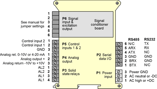
Pinout

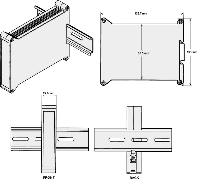
Dimensions

Dimensioned CAD assembly drawings in EPRT, STEP, x_t, .dwg, pdf file formats: Laureate-transmitter-case.zip (zipping prevents browser from opening CAD files as text files).


