New Front Panel USB-C Port Coming Soon!
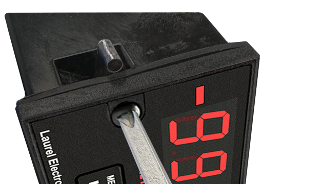
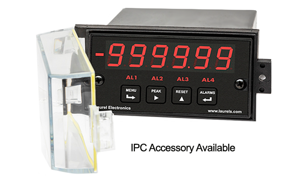

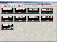
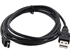
Easy USB-C Programming: Configure a Laureate digital panel meter through the front-panel USB-C port with Laurel’s free Instrument Setup Software for Windows. Meters with a data interface board can also be programmed through that interface. The software shows only the settings that apply to your installed option boards, and configurations can be saved to the meter, a PC, a file server, or a USB thumb drive. Laurel’s free Instrument Setup Software can also be used for light-duty data collection.
All signal conditioner board ranges are factory-calibrated, with calibration factors for each range securely stored in an onboard EEPROM. These factors can be scaled via software to accommodate external shunts, enabling field replacement of signal conditioner boards without necessitating recalibration of the associated digital panel meter. For optimal accuracy, factory recalibration is recommended annually. All Laurel Electronics instruments undergo factory calibration using the industry-leading Fluke calibrators, which are recalibrated yearly and certified traceable to national standards, ensuring the highest level of precision and reliability.
The Laureate Phase Angle & Power Factor Digital Panel Meter utilizes the Laureate Extended counter main board and the FR dual-channel signal conditioner board, which accepts AC signals from 12 mV p-p to 250 Vrms.
Peak and valley values are automatically captured. These may be displayed via a front panel pushbutton command or control signal at the rear connector, or be transmitted as serial data.
Two rear panel control Inputs (CMOS/TTL levels, logic 0 = tied to digital ground, logic 1 = open) or dry contacts that can be set to control / activate 14 meter commands.
An (isolated) 5, 10, 12, or 24 Vdc excitation output is standard to power transducers or two-wire transmitters. Ratiometric operation, which automatically compensates for changes in the applied excitation, is jumper selectable for applications, such as bridges, where the signal to be measured is proportional to the excitation level.
| Phase Angle Mode | |
|---|---|
| Item Displayed | Phase angle difference between two waves of same period |
| Display Units | 1°, 0.1°, 0.01° |
| Frequency Range | 0.005 Hz to 10 kHz |
| Resolution | 0.01°, 1 Hz to 100 Hz; 0.1° at 1 kHz; 1° at 10 kHz |
| Accuracy | 0.05° at 50 or 60 Hz |
| Maximum Timing Interval | 200 sec |
| Power Factor Mode | |
| Item Displayed | Power factor between two sine waves of same period |
| Display Units | 1.000 to 0.000 |
| Polarity | Negative sign indicates negative phase angle |
| Frequency Range | 0.005 Hz to 10 kHz |
| Accuracy | 0.1% at power line frequencies |
| Update Rate | |
| Timing Interval | Gate time + 30 ms+ 0-2 signal periods |
| Gate Time | Selectable 10 ms to 199.99 s |
| Time Before Zero Out | Selectable 10 ms to 199.99 s (to indicate loss of signal) |
| Display | |
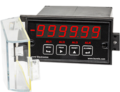
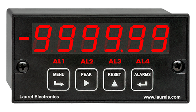
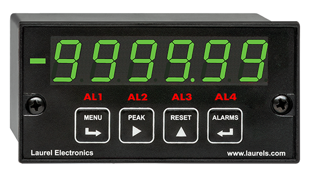
| Readout | 6 LED digits, 7-segment, 14.2 mm (.56"), red or green. |
| Range | -999,999 to +999,999 |
| Indicators | Minus sign, 4 red LED lamps |
| Front-Panel Port | USB-C (programming & data) |
| Protocols | Laurel Custom ASCII (serial), Modbus RTU (serial), Modbus TCP (Ethernet or WiFi) |
| Digital addresses | 247 (Modbus), 31 (Laurel Custom ASCII) |
| Isolation | 250V rms working, 2.3 kV rms per 1 min test |
| Inputs | |
| Signal ranges | Nine AC signal ranges from 12 mVp-p to 250 Vac |
| Signal ground | Common ground for channels A & B |
| Noise filter | 1 MHz, 30 kHz, 250 Hz (jumper selectable) + digital filter |
| Recalibration: All ranges are calibrated at the factory. Recalibration is recommended every 12 months. | |
| Power Supply Boards (one required) | |
| Voltage, standard | 85-264 Vac or 90-300 Vdc |
| Voltage, optional | 12-32 Vac or 10-48 Vdc |
| Frequency | DC or 47-63 Hz |
| Power consumption (typical, base meter) | 1.2W @ 120 Vac, 1.5W @ 240 Vac, 1.3W @ 10 Vdc, 1.4W @ 20 Vdc, 1.55W @ 30 Vdc, 1.8W @ 40 Vdc, 2.15W @ 48 Vdc |
| Power Isolation | 250V rms working, 2.3 kV rms per 1 min test |
| Excitation Output (standard) | |
| 5 Vdc | 5 Vdc ± 5%, 100 mA (jumper selectable) |
| 10 Vdc | 10 Vdc ± 5%, 120 mA (jumper selectable) |
| 12 Vdc | 12 Vdc ± 5%, 100 mA (jumper selectable) |
| 24 Vdc | 24 Vdc ± 5%, 50 mA (jumper selectable) |
| Output Isolation | 50 Vdc from signal ground |
| Analog Output Boards (one optional) | |
| Output levels | 4-20 mA, 0-20 mA, 0-10V, -10 to +10V (jumper selectable) |
| 4-20 mA, 0-20 mA, 0-10V (dual-output option) | |
| Current compliance | 2 mA at 10V ( > 5 kΩ load) |
| Voltage compliance | 12V at 20 mA (< 600 Ω load) |
| Scaling | Zero and full scale adjustable from -99999 to +99999 |
| Resolution | 16 bits (0.0015% of full scale) |
| Isolation | 250V rms working, 2.3 kV rms per 1 min test |
| Relay Output Boards (one optional) | |
| Dual magnetic relays | 2 Form C, 10A max, 440Vac or 125Vdc max, 2500VA or 300W |
| Quad magnetic relays | 4 Form A (NO), 10A max, 440Vac or 125Vdc max, 2500VA or 300W |
| Dual solid state relays | 2 Form A (NO), AC or DC, 0V - 400V, 120Ma, 35Ohms (max at On-State) |
| Quad solid state relays | 4 Form A (NO), AC or DC, 0V - 400V, 120Ma, 35Ohms (max at On-State) |
| Relay commons | Isolated commons for dual relays or each pair of quad relays |
| Relay isolation | 250V rms working, 2.3 kV rms per 1 minute test |
| Relay latching modes | Latching or non-latching |
| Relay active modes | Active on or off, active high or low |
| Hysteresis modes | QA passband mode, split hysteresis, span hysteresis |
| Communication Boards (one optional) | |
| Board selections | L232 (RS232), L485 (RS485, dual RJ11 connectors), LMOD (RS485, dual RJ45 connectors, not for new design), LUSB (USB-C), LUSB485 (USB-C-to-RS485 gateway), LNET (Ethernet), LNET485 (Ethernet-to-RS485 gateway), LNET1 (Ethernet + USB-C), LNET1485 (Ethernet + RS485 slave or gateway), LWIFI (WiFi + USB-C) internal antenna, LWIFIX (WiFi + USB-C) external antenna, LWIFI485 (WiFi + USB-C + RS485 slave or gateway) internal antenna, LWIFIX485 (WiFi + USB-C + RS485 slave or gateway) external antenna |
| Protocols | Laurel Custom ASCII (serial), Modbus RTU (serial), Modbus TCP (Ethernet or WiFi) |
| Digital addresses | 247 (Modbus), 31 (Laurel ASCII), |
| Isolation | 250V rms working, 2.3 kV rms per 1 min test |
| Environmental | |
| Operating temperature | -40°C to 70°C (-40°F to 158°F) |
| Storage temperature. | -40°C to 85°C (-40°F to 185°F) |
| Relative humidity | 95% at 40°C, non-condensing |
| Protection | NEMA-4X (IP-65) when panel mounted |
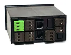
| Electrical Connections | |
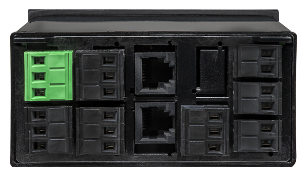
 |
|
| Mechanical | |
| Enclosure | 1/8 DIN, high impact plastic, UL 94V-0, color: black |
| Mounting | 1/8 DIN panel cutout required: 3.622" x 1.772" (92 mm x 45 mm). |
| Dimensions | 4.68" x 2.45" x 5.64" (119 mm x 62 mm x 143 mm) (W x H x D) |
| Maximum panel thickness | 4.5 mm (0.18") |
| Tightening Torque - Connectors | Screw terminal connectors: 5 lb-in (0.56 Nm) |
| Tightening Torque - Pawls | Digital Panel Meter Case Pawls: 5 lb-in (0.56 Nm) |
| Weight of base meter | 210 g (7.4 oz) typical (DPM, counter, timer, 6-digit remote display) |
| Weight of option boards | 30 g (1.0 oz) typical per board (analog output, relay output, communications) |
| General | |
| Programming Methods | Four front panel buttons or via Laurel's free Instrument Setup Software, which runs on a PC under MS Windows. |
| Security | Lockout options include using the front panel buttons, the free Instrument Setup Software, or a hardware jumper. |
| Warranty | 3 years parts & labor |
| Recalibration: All ranges are calibrated at the factory. Recalibration is recommended every 12 months. | |
|
|
| 1/8 DIN Digital Panel Meters | DIN Rail Transmitters |
Free Downloadable Windows-based Instrument Setup (IS) software (Data Interface Board Required) for use with our programmable Digital Panel Meters, Scale Meters, Counters, Timers, Remote Displays, and Transmitters, are an easy method to set up Laureate 1/8 DIN digital panel meters, counters, timers, remote displays, and DIN-rail transmitters, as explained in the Instrument Setup Software Manual. Laureate 1/8 DIN instruments can also be set up from the front panel, as explained in their respective Owners Manuals. Instrument Setup software is of benefit whether or not the PC is connected to the instrument.
Set User Account Control (UAC) of MS Windows to "Never notifiy me" so that Instrument Setup Software can create directories. The UAC change screen can be reached as follows:
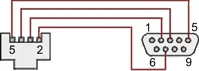
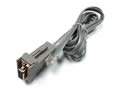
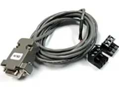
RJ11-to-DB9 cable with rear view of DB9 connector to PC
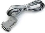
RS232 cable, meter to PC, P/N CBL01
Laureate 1/8 DIN Laureate instruments must be equipped with a serial communications board and be connected to the computer via a serial communications cable. The connection can be via RS232, RS485, USB or Ethernet. Following setup, the serial communications board may be removed from the instrument if desired. The wiring of the RS232 cable is illustrated above with end views of the two connectors.
Laureate LT Series transmitters come standard with a 3-wire serial interface, which can be jumpered for RS232 or RS485.
Laureate LTE Series transmitters come standard with an Ethernet interface.
Click on any of the reduced screens below for a full-size screen view, then click on the Back button of your browser to return to this page. The screens examples below are for a fully-loaded Series 2 Digital Panel Meter (DPM), which is connected to the PC via RS232. If the meter is a Series 1 meter (pre-2007), this is sensed by the software, and somewhat different screens are brought up. Please see Series 1 setup screens.


From the Main Menu, click on Readings if your PC is connected to the meter. A pull-down menu then offers three choices: List, Plot and Graph.


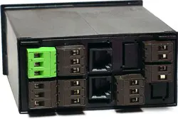


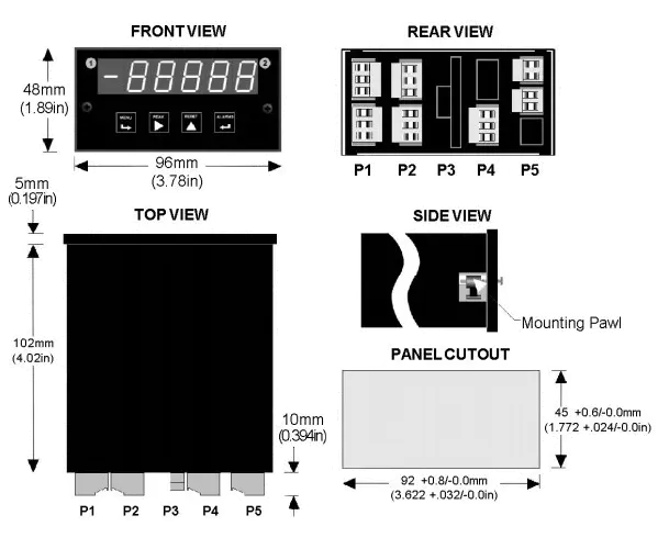
Maximum panel thickness: 4.5 mm (0.18")
Weight of base meter: 210 g (7.4 oz) typical (DPM, counter, timer, 6-digit remote display)
Weight of option boards: 30 g (1.0 oz) typical per board (analog output, relay output, communications)
Tightening Torque - Connectors: Screw terminal connectors: 5 lb-in (0.56 Nm)
Tightening Torque - Pawls: Digital Panel Meter Case Pawls: 5 lb-in (0.56 Nm)
Dimensioned CAD assembly drawings in EPRT, STEP, x_t. dwg, pdf file formats: Laureate-meter-case.zip (zipping prevents browser from opening CAD files as text files).
 Slide the meter into a 45 x 92 mm 1/8 DIN panel cutout. Ensure that the provided gasket is in place between the front of the panel and the back of the meter bezel.
The meter is secured by two pawls, each held by a screw, as illustrated. Turning each screw counterclockwise extends the pawl outward from the case and behind the panel. Turning each screw clockwise further tightens it against the panel to secure the meter.
Slide the meter into a 45 x 92 mm 1/8 DIN panel cutout. Ensure that the provided gasket is in place between the front of the panel and the back of the meter bezel.
The meter is secured by two pawls, each held by a screw, as illustrated. Turning each screw counterclockwise extends the pawl outward from the case and behind the panel. Turning each screw clockwise further tightens it against the panel to secure the meter.
Turning each screw counterclockwise loosens the pawl and retracts it into its well. This position allows installed meter to be removed from their panel, or new meters to be installed in a panel. Do not remove the screws from their pawls. Doing so would cause the screw and pawl to fall off and likely get lost. Do not overtighten so as not to damage the plastic parts.
| Optimizing Meter Inputs for Phase Angle & Power Factor Measurement |
|---|
|
Phase angle and power factor measurement with the Laureate™ Phase Angle & Power Factor Meter require that two signals of identical periods be applied to Channels A and B. For best accuracy, both signals should have the same amplitude, the signal amplitude should be larger than 1V, and the trigger level should be minimized by selecting the ±12 mV jumper position. The meter times zero crossings to 0.1 µs resolution over a user-selectable gate time from 10 ms to 199.99 s. By selecting the minimum gate time of 10 ms, the meter update rate will be approximately 20/s for 50/60 Hz AC line frequency. Improved accuracy will be obtained by making the gate time long enough so that multiple cycles are averaged. Both signals applied to the meter should be mutually isolated by transformer coupling, so that they can then share the same ground in the meter. The current signal is typically obtained from a current transformer (CT). This should ideally be a CT with a voltage output or a current output in the mA range, which can then be converted to a voltage higher than 1V across an external dropping resistor without excessive heat generation. |
| Using Laureate Meters and Counters to Synchronize Motor Generators |
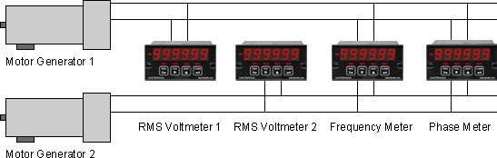
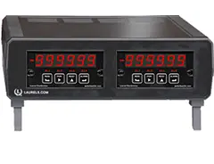
Synchronization of two motor generators requires that the two frequencies be identical, that the lines be in phase, and that the line voltages be close to each other. In this illustration, a single Laureate dual channel counter measures both frequencies to six-figure accuracy in a few line cycles. Another Laureate dual channel counter measures phase angle to 0.1° resolution. Two Laureate AC RMS Voltmeters, which offer ranges of 200.00 V and 600.0 V, are used to display the two RMS voltages to 0.1% accuracy. |
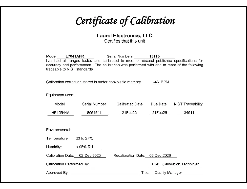
CAL-Digital
Certificate of Calibration
$65.00DLS-XLOG2
XLog2 Data logging Software
$495.00IPC
Digital Panel Meter Splashproof Cover
$55.00CASE1
Digital Panel Meter Benchtop Case1
$150.00CASE2
Digital Panel Meter Benchtop Case2
$150.00BOX1
DPM Enclosure Nema-4x Box1
$180.00BOX2
DPM Enclosure Nema-4x BOX2
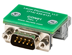
$230.00CON01
CON01 Connector
$75.00CBL6
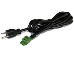
6-foot Power Cable
$41.00CBL12
12-foot Power Cable
$47.00CBL01
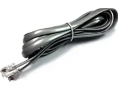
RS232 Cable for Meters
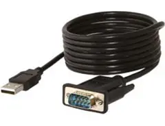
$35.00CBL02
USB-to-RS232 Adapter Cable
$47.00CBL04
RS232 Cable for LT Transmitters
$47.00CBL05
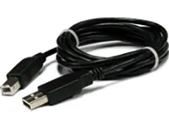
USB Data Cable for Meters
$47.00CBL06
USB-to-RS485 Adapter Cable
$47.00CBL07
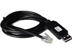
USB Programming & Data Cable
$47.00CBL08
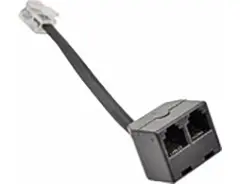
RS485 Splitter Cable
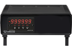
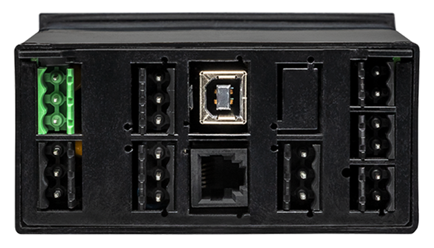
$33.00All boards are isolated from meter and power grounds. Optional Plug-in-Play boards for communications and control include Ethernet, WiFi, serial communication boards, dual or quad relay boards, and an analog output board. Laureates may be powered from 85-264 Vac or optionally from 12-32 Vac or 10-48 Vdc. The display is available with bright red or green 0.56" (14.2mm) high LED digits. The 1/8 DIN case meets NEMA 4X (IP65) specifications from the front when panel mounted. Any setup functions and front panel keys can be locked out for simplified usage and security. A built-in 5, 10, 12, or 24 Vdc excitation supply can power transducers, eliminating the need for an external power supply. All power and signal connections are via UL / VDE / CSA rated screw clamp plugs.
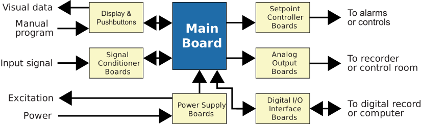
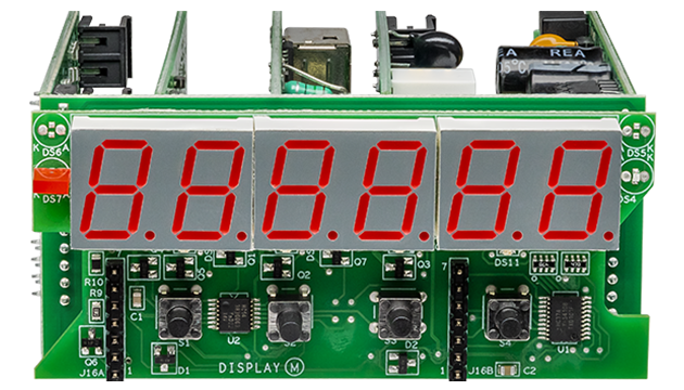
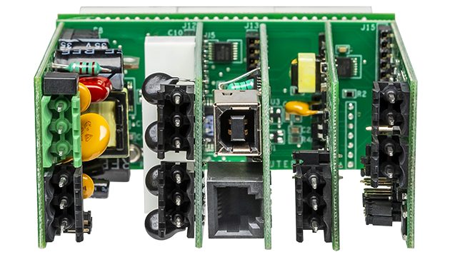
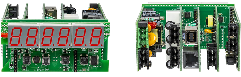
The design of the Laureate™ Series is modular for maximum flexibility at minimum cost. All boards are isolated from meter and power grounds. The base configuration for a digital panel meter or counter consists of a main module (with computer and plug-in display boards), a power supply board, and a signal conditioner board. Optional plug-in-play boards include an isolated setpoint controller board, an isolated analog output board, and an isolated digital interface board. Modular design and a choice of plug-in options allow the Laureate to be customized for a broad range of applications from simple monitoring to control and computer interface. There can be up to five plug-in boards in a 1/8 DIN Laureate.
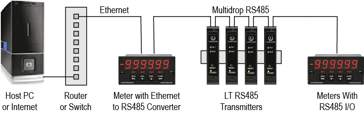
Up to 30 Laureate Digital Panel Meter and/or LT Transmitters can be configured for RS485 and daisy-chained to an LT Transmitter using Laurel’s High Speed Ethernet-to-RS485 converter board for seamless LAN integration. Alternatively, Laurel LTE series Ethernet transmitters can connect directly to a LAN via an Ethernet cable. Setup for both configurations is streamlined using Laurel’s free Instrument Setup Software, which simplifies node discovery and transmitter configuration.
The Laureate Digital Panel Meter can be equipped with Laurel communication boards to support various interfaces and protocols. These include serial interfaces with ASCII or Modbus RTU protocols, and Ethernet interfaces with web access, ASCII, or Modbus TCP/IP protocols, ensuring versatile connectivity for your commercial applications.
The Laureate™ 1/8 DIN Digital Panel Meter for phase angle and power factor computes phase angle θ by timing zero crossings of two signals applied to Channels A and B. Phase angle range is selectable as 0° to 360° or -180° to +180°, with resolution selectable as 1°, 0.1°, or 0.01°. Typical accuracy is 0.01% from 1 Hz to 100 Hz, 0.1% at 1 kHz, and 1% at 10 kHz.
Power factor is the ratio of real power (W) divided by apparent power (VA); for sinusoidal signals differing by phase angle θ, power factor is cos(θ). The meter computes power factor from the measured phase angle, with readings from 1.000 to 0.000 at three decimal places and 0.1% accuracy for sinusoidal signals at 50/60 Hz. While power factor is always positive by definition, the meter artificially assigns a minus sign for negative phase angles, and sets power factor to 0 for phase angles greater than 90°.
Zero crossings are timed to 0.1 µs resolution over a selectable gate time from 10 ms to 199.99 s, with a maximum timing interval of 200 seconds. Frequency range is 0.005 Hz to 10 kHz. Nine AC signal ranges span 12 mV p-p to 250 Vac. Noise filter is jumper-selectable at 1 MHz, 30 kHz, or 250 Hz, plus a digital filter. Time Before Zero Out is separately selectable from 10 ms to 199.99 s, indicating loss of signal.
Phase angle and power factor measurement require two signals of identical period applied to Channels A and B. For best accuracy, both signals should have the same amplitude, amplitude should exceed 1V, and trigger level should be minimized by selecting the ±12 mV jumper position. Both signals should be mutually isolated by transformer coupling so they can share the same ground in the meter. The current signal is typically obtained from a current transformer (CT), ideally one with a voltage output or a mA-range current output that can be converted to a voltage above 1V across an external dropping resistor without excessive heat generation.
Synchronization of two motor generators requires that the two frequencies be identical, the lines be in phase, and the line voltages be close to each other. A single Laureate dual-channel counter can measure both frequencies to six-figure accuracy in a few line cycles; another dual-channel counter measures phase angle to 0.1° resolution; two Laureate AC RMS voltmeters (200.00V and 600.0V ranges) display the two RMS voltages to 0.1% accuracy.
All signal conditioner board ranges are factory-calibrated, with calibration factors stored in EEPROM. Field replacement of the signal conditioner board doesn't require recalibrating the meter. Factory recalibration is recommended annually.
Since the meter times zero crossings to a fixed 0.1 µs resolution, that fixed timing resolution represents a progressively larger fraction of each signal's much shorter period as frequency increases — at 10 kHz the period itself is only 100 µs, so the same absolute 0.1 µs timing uncertainty represents a proportionally much larger share of the measurement, which is why accuracy documented as a percentage degrades at higher frequencies.
Phase and power factor measurement applications span an enormous range of real signal sources — from low-level current transformer outputs in the millivolt range up to full line-voltage signals — and a single fixed sensitivity couldn't reliably trigger cleanly on the smallest signals without risking false triggering on noise for the largest ones, so nine selectable ranges let the trigger threshold match whatever specific signal source is connected.
This documented ceiling caps how long the meter will wait while timing zero crossings for very low-frequency signals before completing a phase or power factor reading — for genuinely very slow signals near the bottom of the documented 0.005 Hz frequency range, this maximum interval sets a practical upper bound on how long a single measurement cycle can take.
No — these are documented as separate, independently selectable settings: gate time governs the timing window used to compute each reading, while Time Before Zero Out specifically indicates loss of signal by zeroing the display if no valid new signal is detected within that separately configured window, rather than affecting the underlying measurement timing itself.
A lower trigger threshold means the meter registers a zero crossing closer to the signal's true zero-voltage point rather than waiting for the signal to rise further above zero — since phase angle is derived directly from the timing of these zero crossings, minimizing trigger level reduces a documented source of systematic timing offset that would otherwise bias the phase angle result.
It's documented specifically as a best-accuracy recommendation rather than an absolute requirement — the meter can still function with mismatched amplitudes, but matching amplitude between the two channels, along with keeping both above 1V and minimizing trigger level, is what the documentation specifically identifies as optimizing measurement accuracy rather than being a strict operational prerequisite.
Line current in a power circuit is far too large to apply directly to a sensitive measurement input — a current transformer steps that current down to a safe, low-level signal, and where the CT's own output is in the milliamp range rather than a voltage, a dropping resistor converts that current into a voltage above the meter's 1V best-accuracy threshold, without generating excessive heat in the process.
Each of the three conditions needed for safe synchronization — matched frequency, matched phase, and matched voltage — is documented as requiring its own specialized measurement technique: dual-channel frequency counting for the frequencies, dedicated phase angle timing for the phase relationship, and dedicated AC RMS voltmeters for the voltage levels, rather than one instrument type being suited to measure all three simultaneously.
Documented specification lists the jumper-selectable noise filter alongside a separate digital filter as complementary layers rather than mutually exclusive options — the jumper-selectable hardware filter addresses high-frequency electrical noise on the incoming signal before it reaches the zero-crossing timing circuitry, while the digital filter operates on the resulting readings, so both can be applied together for a signal that needs both types of noise rejection.
These are documented as independent behaviors — the phase angle mode continues reporting the actual measured angle across its full selectable range (0° to 360° or -180° to +180°) regardless of magnitude, while the power factor calculation specifically clips to 0 beyond 90° because that reflects the genuine mathematical behavior of cos(θ) becoming negative past 90°, which the meter's power factor display isn't designed to represent as a negative real-power value in that region.
Documented practice specifically identifies matching voltage magnitude, frequency, phase angle, and phase sequence (rotation) as the required conditions — all four must fall within acceptable limits simultaneously before a breaker is closed to connect the two sources, since matching only some of these conditions still risks damaging inrush current or mechanical stress.
Documented instrument description specifically explains that a synchroscope's rotating needle speed indicates the frequency difference between the two sources being synchronized, while the needle's position (specifically the 12 o'clock position) indicates the phase angle — a slow-moving needle approaching 12 o'clock is documented as the signal that it's nearly time to close the breaker.
Documented protective-relay guidance specifically describes the synchro check relay as continuously and automatically verifying voltage magnitude, frequency, and phase angle are within acceptable limits, providing a permissive signal that prevents breaker closure under out-of-sync conditions — this serves as either the primary automatic synchronizing method or as an independent safety backup layered on top of manual synchroscope-based operation.
Documented consequences specifically describe a sudden current surge and significant mechanical stress on rotating equipment when unsynchronized systems are connected — this is documented as capable of disturbing or severely damaging one or both connected systems, which is the fundamental reason synchronization verification exists as a required step before paralleling.
Documented guidance specifically recommends checking phase sequence for both the generator and grid busbars using the same phase sequence meter each time — while phase sequence itself is generally a fixed wiring characteristic rather than something that drifts, documented practice treats verification as a standard part of the synchronization preparation sequence, catching wiring changes or errors before they cause a problem.
No — documented analysis specifically notes that once two sources are disconnected after having been paralleled, generator frequency is likely to drift again over time, meaning ongoing monitoring and adjustment remain necessary to maintain synchronization for any future reconnection, rather than treating a single successful synchronization event as a permanent state.
No — documented guidance specifically states that only generators and generator sets specifically designed and equipped for parallel operation can be synchronized, requiring a dedicated control system, a suitable circuit breaker, and protective relays such as a sync check relay; a standard portable generator not built for this purpose is documented as not suitable for paralleling.
Not entirely — documented guidance specifically notes that despite advances in automatic synchronizing technology, manual synchronization using synchroscopes and synchronizing lamps remains a widely used method, particularly in smaller power generation setups or backup systems, with automatic sync check relays commonly serving as a safety backup layered onto manual procedures rather than fully replacing them.