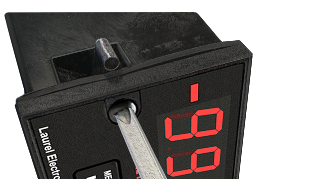
New Front Panel USB-C Port Coming Soon!
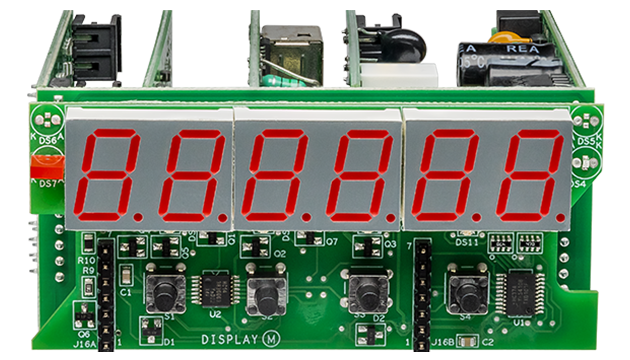
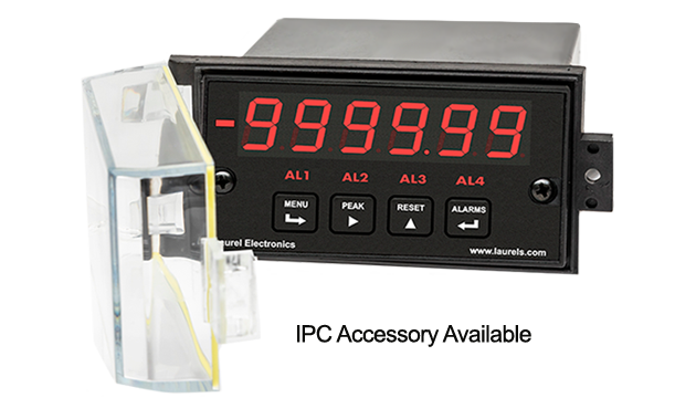
Three items are tracked by the batch control software. These can each be scaled to engineering units of total or flow rate and displayed by the controller's six-digit LED display: Item #1 is the current batch total, which can be set up to count up from zero to a preset limit, or down from a preset limit to zero. Item #2 can be assigned to grand total or number of batches. Item #3 is the flow rate.
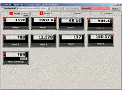
Easy USB-C Programming: Configure a Laureate digital panel meter through the front-panel USB-C port with Laurel’s free Instrument Setup Software for Windows. Meters with a data interface board can also be programmed through that interface. The software shows only the settings that apply to your installed option boards, and configurations can be saved to the meter, a PC, a file server, or a USB thumb drive. Laurel’s free Instrument Setup Software can also be used for light-duty data collection.
All signal conditioner board ranges are factory-calibrated, with calibration factors for each range securely stored in an onboard EEPROM. These factors can be scaled via software to accommodate external shunts, enabling field replacement of signal conditioner boards without necessitating recalibration of the associated digital panel meter. For optimal accuracy, factory recalibration is recommended annually. All Laurel Electronics instruments undergo factory calibration using the industry-leading Fluke calibrators, which are recalibrated yearly and certified traceable to national standards, ensuring the highest level of precision and reliability.
Two or four relays can be used. Relay #1 is assigned to batch total to control the filling operation. Relays #2, #3 and #4 can each be assigned by the user to Items #1, #2 or #3. For example, Relay #2 can be assigned to Item #1 (batch total) with a lower setpoint to serve as a pre-warn and slow down the fill rate near the batch setpoint, and Relay #3 can be assigned to the total number of batches to terminate the batching when a present number of bottles have been filled.
An optional serial communications board allows the batch controller to transmit Items #1, #2 and #3, as well as peak for item #3 (rate). If required, all four items can be displayed simultaneously by augmenting the batch controller with up to three Laureate remote displays. Each of these can have its own analog output and relays for alarm or control.
The analog input batch controller utilizes the Laureate VF voltage-to-frequency converter signal conditioner board, which converts 4-20 mA, 0-1 mA or 0-1V conditioned flow meter signals to a frequency from 10 kHz to 110 kHz. This allows the counter controller to totalize flow, to count up to a preset value, or to count down to zero from a preset value for batch control. One of the relays is dedicated to On/Off batch control, while the other relay is available to slow down rate near the setpoint or to provide another alarm or control function based on rate or total.
Peak and valley values are automatically captured. These may be displayed via a front panel pushbutton command or control signal at the rear connector, or be transmitted as serial data.
Two rear panel control Inputs (CMOS/TTL levels, logic 0 = tied to digital ground, logic 1 = open) or dry contacts that can be set to control / activate 14 meter commands.
An (isolated) 5, 10, 12, or 24 Vdc excitation output is standard to power transducers or two-wire transmitters. Ratiometric operation, which automatically compensates for changes in the applied excitation, is jumper selectable for applications, such as bridges, where the signal to be measured is proportional to the excitation level.
| Display | |
|---|---|
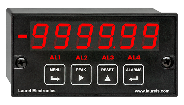
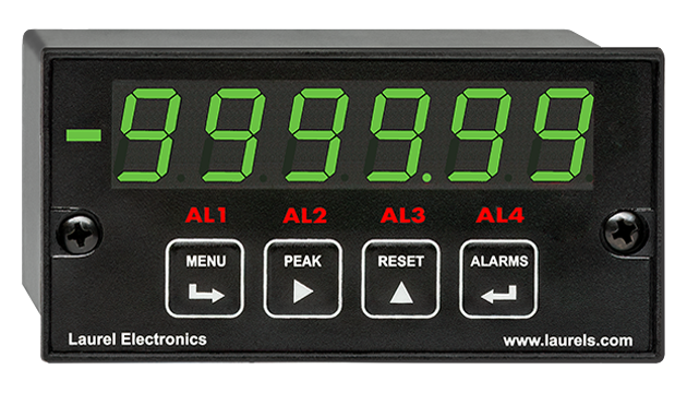
| Readout | 6 LED digits, 7-segment, 14.2 mm (.56"), red or green |
| Display Range | -999,999 to +999,999, XXXXEX scientific notation beyond 999,999 |
| Zero Adjust | -999,999 to +999,999 |
| Span Adjust | 0 to ±999,999 |
| Indicators | Minus sign, 4 red LED lamps |
| Front-Panel Port | USB-C (programming & data) |
| Protocols | Laurel Custom ASCII (serial), Modbus RTU (serial), Modbus TCP (Ethernet or WiFi) |
| Digital addresses | 247 (Modbus), 31 (Laurel Custom ASCII) |
| Isolation | 250V rms working, 2.3 kV rms per 1 min test |
| Analog Input (V-to-F signal conditioner) | |
| Signal Types | 0-1 mA, 4-20 mA, 0-10V |
| Conversion Technique | Inverse period applied to 10 kHz- 110 kHz |
| Update Rate | 50 ms (max) |
| Gate Time | Selectable 10 ms to 199.99 s |
| Recalibration: All ranges are calibrated at the factory. Recalibration is recommended every 12 months. | |
| Power Supply Boards (one required) | |
| Voltage, standard | 85-264 Vac or 90-300 Vdc |
| Voltage, optional | 12-32 Vac or 10-48 Vdc |
| Frequency | DC or 47-63 Hz |
| Power consumption | 1.2W @ 120 Vac, 1.5W @ 240 Vac, 1.3W @ 10 Vdc, 1.4W @ 20 Vdc, |
| (typical, base meter) | 1.55W @ 30 Vdc, 1.8W @ 40 Vdc, 2.15W @ 48 Vdc |
| Power Isolation | 250V rms working, 2.3 kV rms per 1 min test |
| Excitation Output (standard) | |
| 5 Vdc | 5 Vdc ± 5%, 100 mA (jumper selectable) |
| 10 Vdc | 10 Vdc ± 5%, 120 mA (jumper selectable) |
| 12 Vdc | 12 Vdc ± 5%, 100 mA (jumper selectable) |
| 24 Vdc | 24 Vdc ± 5%, 50 mA (jumper selectable) |
| Output Isolation | 50 Vdc from signal ground |
| Analog Output Boards (one optional) | |
| Output Levels | 4-20 mA, 0-20 mA, 0-10V, -10 to +10V (single-output option) |
| Current compliance | 4-20 mA, 0-20 mA, 0-10V (dual-output option) |
| Voltage compliance | 2 mA at 10V ( > 5 kΩ load) |
| Scaling | 12V at 20 mA ( < 600 Ω load) |
| Resolution | Zero and full scale adjustable from -99999 to +99999 16 bits (0.0015% of full scale) |
| Isolation | 250V rms working, 2.3 kV rms per 1 min test (dual analog outputs share the same ground) |
| Relay Output Boards (one required for batch control) | |
| Dual magnetic relays | 2 Form C, 10A max, 440Vac or 125Vdc max, 2500VA or 300W |
| Quad magnetic relays | 4 Form A (NO), 10A max, 440Vac or 125Vdc max, 2500VA or 300W |
| Dual solid state relays | 2 Form A (NO), AC or DC, 0V - 400V, 120Ma, 35Ohms (max at On-State) |
| Quad solid state relays | 4 Form A (NO), AC or DC, 0V - 400V, 120Ma, 35Ohms (max at On-State) |
| Relay commons | Isolated commons for dual relays or each pair of quad relays |
| Relay isolation | 250V rms working, 2.3 kV rms per 1 minute test |
| Relay latching modes | Latching or non-latching |
| Relay active modes | Active on or off, active high or low |
| Hysteresis modes | QA passband mode, split hysteresis, span hysteresis |
| Communication Boards (one optional) | |
| Board Selections | L232 (RS232), L485 (RS485, dual RJ11 connectors), LMOD (RS485, dual RJ45 connectors, not for new design), LUSB (USB-C), LUSB485 (USB-C-to-RS485 gateway), LNET (Ethernet), LNET485 (Ethernet-to-RS485 gateway), LNET1 (Ethernet + USB-C), LNET1485 (Ethernet + RS485 slave or gateway), LWIFI (WiFi + USB-C) internal antenna, LWIFIX (WiFi + USB-C) external antenna, LWIFI485 (WiFi + USB-C + RS485 slave or gateway) internal antenna, LWIFIX485 (WiFi + USB-C + RS485 slave or gateway) external antenna |
| Protocols | Laurel Custom ASCII (serial), Modbus RTU (serial), Modbus TCP (Ethernet or WiFi) |
| Digital Addresses | 247 (Modbus), 31 (Laurel ASCII), |
| Isolation | 250V rms working, 2.3 kV rms per 1 min test |
| Environmental | |
| Operating Temperature | -40°C to 70°C (-40°F to 158°F) |
| Storage Temperature | -40°C to 85°C (-40°F to 185°F) |
| Relative Humidity | 95% at 40°C, non-condensing |
| Protection | NEMA-4X (IP-65) when panel mounted |
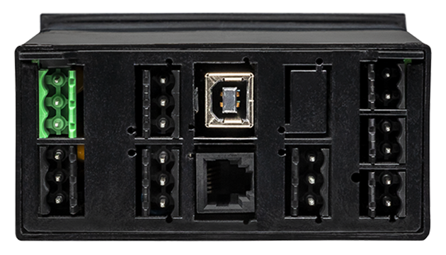
| Signal Connections | |
 |
|
| Mechanical | |
| Enclosure | 1/8 DIN, high impact plastic, UL 94V-0, color: black |
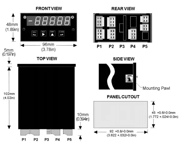
| Mounting | 1/8 DIN panel cutout required: 3.622" x 1.772" (92 mm x 45 mm). |
| Dimensions | 4.68" x 2.45" x 5.64" (119 mm x 62 mm x 143 mm) (W x H x D) |
| Maximum panel thickness | 4.5 mm (0.18") |
| Tightening Torque - Connectors | Screw terminal connectors: 5 lb-in (0.56 Nm) |
| Tightening Torque - Pawls | Digital Panel Meter Case Pawls: 5 lb-in (0.56 Nm) |
| Weight of base meter | 210 g (7.4 oz) typical (DPM, counter, timer, 6-digit remote display) |
| Weight of option boards | 30 g (1.0 oz) typical per board (analog output, relay output, communications) |
| General | |
| Programming Methods | Four front panel buttons or via Laurel's free Instrument Setup Software, which runs on a PC under MS Windows. |
| Security | Lockout options include using the front panel buttons, the free Instrument Setup Software, or a hardware jumper. |
| Warranty | 3 years parts & labor |
| Recalibration: All ranges are calibrated at the factory. Recalibration is recommended every 12 months. | |
|
|
| 1/8 DIN Digital Panel Meters | DIN Rail Transmitters |
Free Downloadable Windows-based Instrument Setup (IS) software (Data Interface Board Required) for use with our programmable Digital Panel Meters, Scale Meters, Counters, Timers, Remote Displays, and Transmitters, are an easy method to set up Laureate 1/8 DIN digital panel meters, counters, timers, remote displays, and DIN-rail transmitters, as explained in the Instrument Setup Software Manual. Laureate 1/8 DIN instruments can also be set up from the front panel, as explained in their respective Owners Manuals. Instrument Setup software is of benefit whether or not the PC is connected to the instrument.
Set User Account Control (UAC) of MS Windows to "Never notifiy me" so that Instrument Setup Software can create directories. The UAC change screen can be reached as follows:
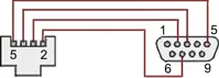
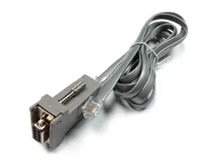
RJ11-to-DB9 cable with rear view of DB9 connector to PC
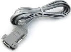
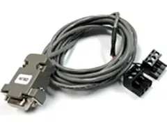
RS232 cable, meter to PC, P/N CBL01
Laureate 1/8 DIN Laureate instruments must be equipped with a serial communications board and be connected to the computer via a serial communications cable. The connection can be via RS232, RS485, USB or Ethernet. Following setup, the serial communications board may be removed from the instrument if desired. The wiring of the RS232 cable is illustrated above with end views of the two connectors.
Laureate LT Series transmitters come standard with a 3-wire serial interface, which can be jumpered for RS232 or RS485.
Laureate LTE Series transmitters come standard with an Ethernet interface.
Click on any of the reduced screens below for a full-size screen view, then click on the Back button of your browser to return to this page. The screens examples below are for a fully-loaded Series 2 Digital Panel Meter (DPM), which is connected to the PC via RS232. If the meter is a Series 1 meter (pre-2007), this is sensed by the software, and somewhat different screens are brought up. Please see Series 1 setup screens.


From the Main Menu, click on Readings if your PC is connected to the meter. A pull-down menu then offers three choices: List, Plot and Graph.




Maximum panel thickness: 4.5 mm (0.18")
Weight of base meter: 210 g (7.4 oz) typical (DPM, counter, timer, 6-digit remote display)
Weight of option boards: 30 g (1.0 oz) typical per board (analog output, relay output, communications)
Tightening Torque - Connectors: Screw terminal connectors: 5 lb-in (0.56 Nm)
Tightening Torque - Pawls: Digital Panel Meter Case Pawls: 5 lb-in (0.56 Nm)
Dimensioned CAD assembly drawings in EPRT, STEP, x_t. dwg, pdf file formats: Laureate-meter-case.zip (zipping prevents browser from opening CAD files as text files).
 Slide the meter into a 45 x 92 mm 1/8 DIN panel cutout. Ensure that the provided gasket is in place between the front of the panel and the back of the meter bezel.
The meter is secured by two pawls, each held by a screw, as illustrated. Turning each screw counterclockwise extends the pawl outward from the case and behind the panel. Turning each screw clockwise further tightens it against the panel to secure the meter.
Slide the meter into a 45 x 92 mm 1/8 DIN panel cutout. Ensure that the provided gasket is in place between the front of the panel and the back of the meter bezel.
The meter is secured by two pawls, each held by a screw, as illustrated. Turning each screw counterclockwise extends the pawl outward from the case and behind the panel. Turning each screw clockwise further tightens it against the panel to secure the meter.
Turning each screw counterclockwise loosens the pawl and retracts it into its well. This position allows installed meter to be removed from their panel, or new meters to be installed in a panel. Do not remove the screws from their pawls. Doing so would cause the screw and pawl to fall off and likely get lost. Do not overtighten so as not to damage the plastic parts.
| Drum Filling Application Utilizing Two Relay Outputs | |
|---|---|
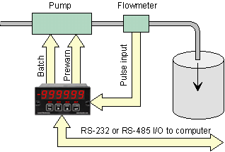 |
In this drum filling application, the Laureate pulse-input batch controller utilizes uses its two relays to control a pump. The Prewarn relay slows down the pump near the preset to avoid overshoot. The Batch relay stops the pump at the preset. |
| Controlling Chemical Mixing of Materials | |
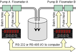 |
Multiple Laureate batch controllers can be used in combination to control the mixing of materials in the proper ratio. Each feed line is equipped with its own pump, flowmeter, and Laureate. Controller setup and monitoring of the mixing operation are facilitated by optional serial communications. RS485 allows a single data line to handle multiple controllers. |
| Up-Counting Batch Control | |
 |
In up-counting batch control, the Laureate counts up from zero to a preset maximum. A prewarn level is available to slow down filling near the preset to avoid overshoot. A time delay can be programmed from the end of each batch to the start of the next batch. |
| Down-Counting Batch Control | |
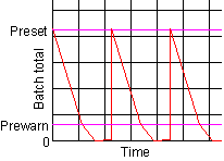 |
In down-counting batch control, the Laureate counts down from the preset maximum to zero. A prewarn level is available to slow down filling or emptying near zero. Again, a time delay can be programmed from the end of each batch to the start of the next batch. |
| Discrete Filling and Batch Counting | |
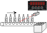 |
The Laureate batch controller is ideal for discrete manufacturing as well as repetitive fill operations. In this example, the Laureate counts bottles which it then groups into sixpacks. Its Grand Total capability can be used to track bottles or sixpacks. |
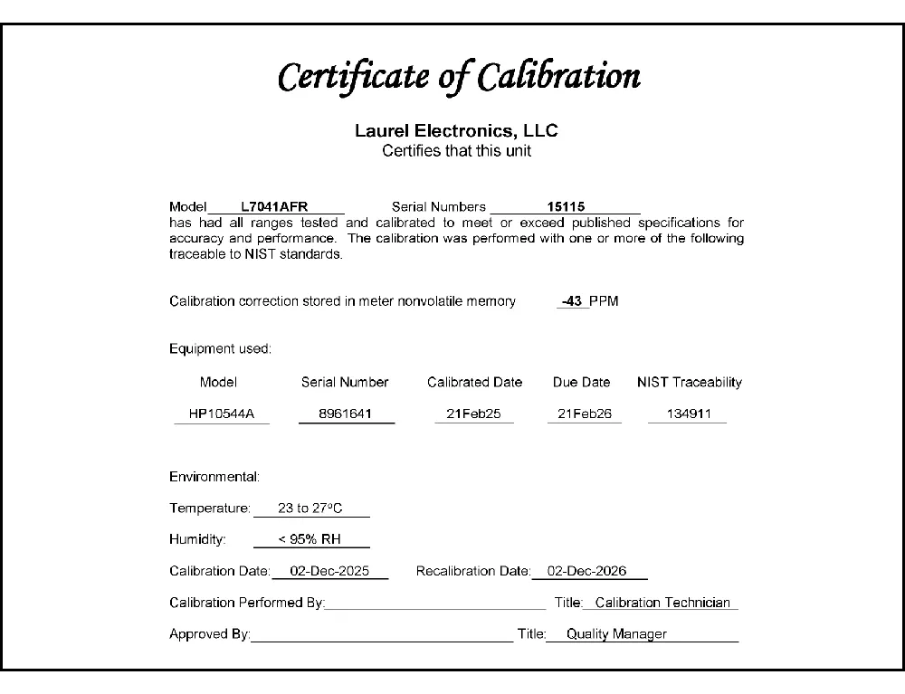
CAL-Digital
Certificate of Calibration
$65.00DLS-XLOG2
XLog2 Data logging Software
$495.00IPC
Digital Panel Meter Splashproof Cover
$55.00CASE1
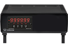
Digital Panel Meter Benchtop Case1
$150.00CASE2
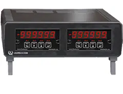
Digital Panel Meter Benchtop Case2
$150.00BOX1
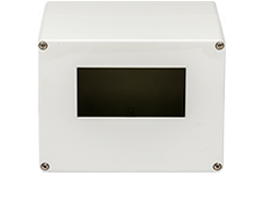
DPM Enclosure Nema-4x Box1
$180.00BOX2
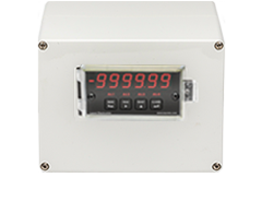
DPM Enclosure Nema-4x BOX2
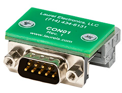
$230.00CON01
CON01 Connector
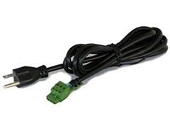
$75.00CBL6
6-foot Power Cable
$41.00CBL12
12-foot Power Cable
$47.00CBL01
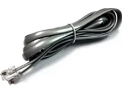
RS232 Cable for Meters
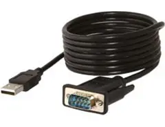
$35.00CBL02
USB-to-RS232 Adapter Cable
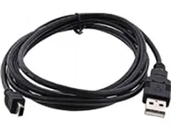
$47.00CBL04
RS232 Cable for LT Transmitters
$47.00CBL05
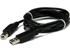
USB Data Cable for Meters
$47.00CBL06
USB-to-RS485 Adapter Cable
$47.00CBL07
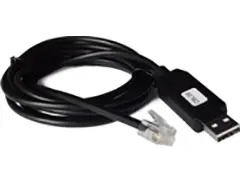
USB Programming & Data Cable
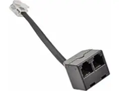
$47.00CBL08
RS485 Splitter Cable
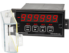
$33.00All boards are isolated from meter and power grounds. Optional Plug-in-Play boards for communications and control include Ethernet, WiFi, serial communication boards, dual or quad relay boards, and an analog output board. Laureates may be powered from 85-264 Vac or optionally from 12-32 Vac or 10-48 Vdc. The display is available with bright red or green 0.56" (14.2mm) high LED digits. The 1/8 DIN case meets NEMA 4X (IP65) specifications from the front when panel mounted. Any setup functions and front panel keys can be locked out for simplified usage and security. A built-in 5, 10, 12, or 24 Vdc excitation supply can power transducers, eliminating the need for an external power supply. All power and signal connections are via UL / VDE / CSA rated screw clamp plugs.
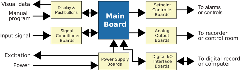
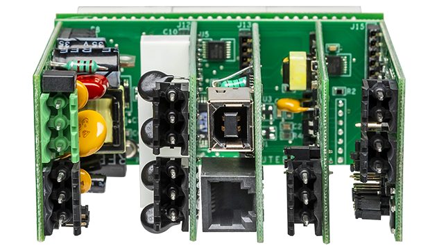
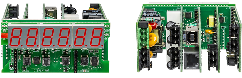
The design of the Laureate™ Series is modular for maximum flexibility at minimum cost. All boards are isolated from meter and power grounds. The base configuration for a digital panel meter or counter consists of a main module (with computer and plug-in display boards), a power supply board, and a signal conditioner board. Optional plug-in-play boards include an isolated setpoint controller board, an isolated analog output board, and an isolated digital interface board. Modular design and a choice of plug-in options allow the Laureate to be customized for a broad range of applications from simple monitoring to control and computer interface. There can be up to five plug-in boards in a 1/8 DIN Laureate.
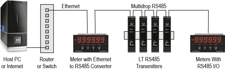
Up to 30 Laureate Digital Panel Meter and/or LT Transmitters can be configured for RS485 and daisy-chained to an LT Transmitter using Laurel’s High Speed Ethernet-to-RS485 converter board for seamless LAN integration. Alternatively, Laurel LTE series Ethernet transmitters can connect directly to a LAN via an Ethernet cable. Setup for both configurations is streamlined using Laurel’s free Instrument Setup Software, which simplifies node discovery and transmitter configuration.
The Laureate Digital Panel Meter can be equipped with Laurel communication boards to support various interfaces and protocols. These include serial interfaces with ASCII or Modbus RTU protocols, and Ethernet interfaces with web access, ASCII, or Modbus TCP/IP protocols, ensuring versatile connectivity for your commercial applications.
The Laureate™ 1/8 DIN Digital Panel Meter batch controller is a low-cost, highly accurate controller for repetitive fill operations, using the Laureate V-to-F analog signal conditioner for 4-20 mA, 0-1 mA, or 0-10V conditioned flow meter signals. Relay control is provided by two or four 8A contact relays, or two or four 120 mA AC/DC solid state relays. Fill operations repeat continually with a programmable delay from 10 ms to 199.99 sec, or based on an external control input.
Item #1 is the current batch total, set up to count up from zero to a preset limit, or down from a preset limit to zero. Item #2 can be assigned to grand total or number of batches. Item #3 is the flow rate. Each can be scaled to engineering units and displayed on the six-digit LED display.
The analog input batch controller uses the Laureate VF voltage-to-frequency converter signal conditioner board, converting 4-20 mA, 0-1 mA, or 0-10V conditioned flow meter signals to a frequency from 10 kHz to 110 kHz. This lets the counter totalize flow, count up to a preset value, or count down to zero from a preset value for batch control. One relay is dedicated to On/Off batch control, while the other relay is available to slow down rate near the setpoint or provide another alarm or control function based on rate or total. Update rate is 50 ms maximum, with gate time selectable from 10 ms to 199.99 s.
Relay #1 is assigned to batch total to control the filling operation. Relays #2, #3, and #4 can each be assigned by the user to Items #1, #2, or #3. For example, Relay #2 can be assigned to Item #1 with a lower setpoint to serve as a pre-warn and slow the fill rate near the batch setpoint, and Relay #3 can be assigned to the total number of batches to terminate batching once a preset number of containers has been filled.
An optional serial communications board transmits Items #1, #2, and #3, plus peak for Item #3 (rate). If all four values are needed simultaneously, the batch controller can be augmented with up to three Laureate remote displays, each with its own analog output and relays for alarm or control.
All signal conditioner board ranges are factory-calibrated, with calibration factors stored in EEPROM. Field replacement of the signal conditioner board doesn't require recalibrating the meter. Factory recalibration is recommended annually.
The VF signal conditioner first converts the single 4-20 mA, 0-1 mA, or 0-10V signal into a frequency between 10 kHz and 110 kHz — from that point, the Extended counter's internal batch-control logic derives both the accumulated total and the instantaneous rate from that single converted frequency stream, rather than needing two physically separate channels the way the pulse-input version does.
Since the analog signal is first converted to a stable, predictable 10 kHz to 110 kHz frequency band by the VF converter — rather than accepting a widely variable raw pulse train directly — the timing math needed to derive an update from that converted frequency is inherently more consistent, which is likely why the documented update-rate figure for this analog configuration is expressed as a simpler, single maximum value.
Gate time here specifically governs the trade-off between display stability and responsiveness for the derived rate and total readings — a longer gate time produces smoother rate readings with less noise-driven variation, while a shorter gate time gives faster response to genuine changes in the incoming analog signal; this tradeoff mirrors the general gate-time behavior documented elsewhere in the Laureate line.
Documented capability specifically describes the VF board accepting "conditioned flow meter signals" in 4-20 mA, 0-1 mA, or 0-10V form — standard 4-20 mA transmitter output is itself already a conditioned, standardized industrial signal type the VF board is designed to accept directly, without requiring additional external signal conditioning equipment.
No — the meter's own front-panel or software-based scaling (using methods such as the coordinates-of-two-points setup) is specifically designed to map whatever the transmitter's actual signal range represents to the desired displayed engineering units, meaning mismatched spans are handled through the meter's internal scaling configuration rather than requiring external hardware.
These three documented options correspond to different standard transmitter output conventions found across various flow meter and transducer product lines — the correct choice depends entirely on which output type the specific connected flow transmitter or transducer actually provides, rather than one option being generally preferable; matching the meter's input option to the transmitter's actual output type is what determines the correct selection.
Both contribute to overall system accuracy — the batch controller's own documented conversion and display accuracy is one factor, but if the connected transmitter's own output isn't perfectly linear across its range, that transmitter-side nonlinearity carries through into the batch total regardless of how accurately the meter itself processes the signal it receives; achieving the best overall batch accuracy depends on both components working together.
Yes — the documented multi-controller chemical mixing application specifically describes using multiple Laureate batch controllers together via RS485, and this general networked architecture applies regardless of whether each individual controller in that network is configured for pulse input or analog input, since RS485 communication and batch control logic operate the same way once the meter has derived its total and rate values.
Since the VF converter continuously translates the analog signal into a corresponding frequency, and the meter's internal processing samples that frequency according to the selected gate time, the displayed total effectively updates in discrete steps whose size is set by the gate time — a shorter gate time produces finer, more frequent updates that more closely track a smoothly changing input, while a longer gate time produces coarser, less frequent steps.
No — the documented three-item tracking structure (Item #1 batch total, Item #2 grand total or batch count, Item #3 rate) and the six-digit display, relay assignment logic, and serial transmission capabilities are all described identically regardless of which signal conditioner board is installed; the VF and FR boards differ specifically in how they acquire and convert the incoming signal, not in how the Extended counter's batch-control logic subsequently processes and displays it.
Documented batch-delivery system design specifically explains that the control valve takes a finite amount of time to shut off after receiving the closure signal, and material already in the delivery path continues reaching the destination even after closure begins — sending the closure signal early, timed to account for both effects, is what allows the final delivered total to land close to the actual target rather than overshooting it.
Documented examples specifically cite control valve closure times on the order of 5 to 10 seconds — for a fast-filling batch process, several seconds of continued flow after the closure signal is sent represents a genuinely significant, non-negligible volume that must be accounted for rather than assumed away.
Documented practice specifically describes performing trial batch runs before beginning production batches — these trials are specifically run to derive the actual overfill behavior for that particular valve, flow rate, and delivery path combination, generating the compensation data the system then applies to subsequent production batches rather than relying on a generic, assumed value.
Yes — documented analysis specifically notes that consistently tracking valve closure timing is also useful for identifying a possible malfunction or incipient malfunction in the control valve itself; a valve whose closure time drifts meaningfully from its established baseline is documented as a detectable early warning sign worth investigating before it causes a genuine batch accuracy failure.
No — documented technical analysis specifically illustrates that a solenoid's movement time and closing/release time differ measurably between a coil temperature of 25°C and 125°C, meaning temperature is a genuine, documented variable affecting valve response timing, not a factor that can be safely assumed constant across all operating conditions.
Yes — a documented resin catalyzation control system specifically describes adding the key ingredient first, then recalculating the target weights for the remaining ingredients based on that key ingredient's actual (possibly overshot) delivered weight — this documented technique maintains the critical ratio between ingredients even when the first ingredient's delivery doesn't land exactly on its original target.
Yes — documented analysis specifically identifies additional contributing factors beyond valve closure time alone, including signal lag time in the control system, the time period between consecutive measurement checks (such as periodic weight readings on a mixing tank), and valve clogging — meaning overshoot compensation calibrated for one specific cause may not fully account for these other, separately documented contributing factors.
Documented guidance specifically presents both as valid approaches depending on required precision — while individually calibrating compensation components for each specific fluidic delivery device is documented as the most accurate method, an alternative documented approach establishes a constant compensation value applied across all devices of a given type, accepted as producing negligible compromise to overall accuracy for less precision-critical applications.