- Description
- Quick Selector Guide
- Specifications
- Setup Software
- Mechanical
- Documents
- Applications
- Accessories
Features
- Two independently field-scalable pulse input channels A and B
- Arithmetic functions A+B, A-B, AxB, A/B, A/B-1 (draw) applicable to rate or total
- Inputs from NPN or PNP proximity switches, contact closures, digital logic, magnetic pickups down to 12 mV, or AC inputs up to 250 Vac
- Two independently field-scalable pulse input channels from 0.005 Hz to 1 MHz
- 4-20 mA, 0-20 mA, 0-10V or -10V to +10V transmitter output, (isolated)
- Analog output resolution 0.0015% of span, accuracy ±0.02% of span
- Ethernet data I/O, Modbus TCP
- Dual 120 mA solid state relays for alarm or control (isolated)
- 5V, 10V, 12V, or 24V dc transducer excitation output (isolated)
- Power 85-264 Vac / 90-300 Vdc or 10-48 Vdc / 12-32 Vac (isolated)
- DIN rail mount housing, 22.5 mm wide, detachable screw-clamp connectors
- Operating temperature from -40°C to 70°C (-40°F to 158°F)
- Extended allows up to 180 data points for custom curve linearization and a rate derived from consecutive readings along with arithmetic functions A+B, A-B, AxB, A/B or A/B-1
Certificates of Compliance
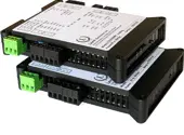
The Laureate™ LTE Series DIN rail analog transmitter with ethernet communication and analog outputs for versatile connectivity.
The digitally programmable transmitter features two relays for alarm or control. The series offers exceptional accuracy with Input frequencies from 0.005 Hz to 1 MHz. The LTE Series transmitters offer the same high performance, signal conditioning, and programmable features as Laureate digital panel meters, counters, and timers.The Laureate 4-20 mA, 0-20 mA, 0-10V or -10V to +10V and ethernet output transmitter for ratio, product, sum or difference of 2 rates or totalsaccepts two independently scalable input channels A & B from a wide range of pulse sources, such as NPN or PNP proximity switches, contact closures, digital logic, magnetic pickups down to 12 mV, or AC voltages to 250 Vac. Input frequencies can range from 0.005 Hz to 1 MHz.
Arithmetic functions A+B, A-B, AxB, A/B or A/B-1 are made available by the Extended counter main board and can track the sum, difference, product, ratio, or draw of both input channels. These functions can be applied to scaled rates, scaled totals, square root of rates, totals after square root extraction, custom curve linearized rates, or totals after custom curve linearization.
- Sum can be used to add two flows for total flow, or to add the number of parts carried by two conveyor belts.
- Difference can be used to subtract outflow from inflow for net flow, or to subtract reject parts from total parts.
- Product can be used to multiply two rates, for example to compute horsepower by multiplying torque by RPM.
- Ratio can be used to compare flow rates in two channels, the RPM of rollers or gears, or the speed of moving machinery, such as conveyor belts. Ratio can also be applied to scaled totals to compare two batches to be mixed. In this application, one transmitter is used to monitor the ratio of flow rates, and a second transmitter to monitor the resulting batch totals.
- Draw is obtained by subtracting 1 from ratio. Draw is used to measure the elongation of material as it passes between rollers, or to monitor variation in the speed of rollers for tensioning.

The Extended Laureate computer board can display rate based on successive readings. It also allows exceptionally accurate custom curve linearization, for example to read out liquid volume or rate of flow in a horizontal cylindrical tank based on level reported by a 4-20 mA transmitter. For setup, up to 180 data points can be input into a computer spreadsheet or text file by the user. The computer then calculates spline-fit segments, which are downloaded into the transmitter.
Exceptional Accuracy and Stability. Laureate transmitters determine frequency by taking the inverse of period as measured with a calibrated quartz crystal time base. This results in extremely accurate and stable 6-digit internal readings (±999,999 counts), which are then processed in software. The analog output is generated by an ultra-linear 16-bit (65,536 step) digital-to-analog converter (DAC) for 0.02% output accuracy. The update rate of the transmitter output is a programmed gate time + 30 ms + 0-2 signal periods. For a 60 Hz signal, the update rate would be 20 per second. Such fast update rates are ideal for alarm and control.
The update rate of the transmitter output is a programmed gate time + 30 ms + 0-2 signal periods. For pulse rates of 60 Hz and above, the update rate would be 20 per second. Such fast update rates are ideal for alarm and control.
All signal conditioner board ranges are factory-calibrated, with calibration factors for each range securely stored in an onboard EEPROM. These factors can be scaled via software to accommodate external shunts, enabling field replacement of signal conditioner boards without necessitating recalibration of the associated transmitter. For optimal accuracy, factory recalibration is recommended annually. All Laurel Electronics instruments undergo factory calibration using the industry-leading Fluke calibrators, which are recalibrated yearly and certified traceable to national standards, ensuring the highest level of precision and reliability.
Laureate Transmitters are easily programmed with Laurel’s free Instrument Setup Software, downloadable from our website and compatible with Windows PCs, requiring a data interface board for setup.
Standard Features of Laureate LTE Transmitters Include:
- Ethernet I/O, (isolated). The supported protocols are Modbus RTU and ASCII, which are tunneled via Modbus TCP. Note that RS232 or RS485 data I/O is provided by Laurel's LT Series transmitters.
- 4-20 mA, 0-20 mA or 0-10V analog transmitter output, (isolated), jumper-selectable and user scalable. All selections provide 16-bit (0.0015 ) resolution of output span and 0.02% output accuracy of a reading from -99,999 to +99,999 counts that is also transmitted digitally. Output isolation from signal and power grounds eliminates potential ground loop problems. The supply can drive 20 mA into a 500 ohm (or lower) load for 10V compliance, or 10V into a 5K ohm (or higher) load for 2 mA compliance.
- Dual-channel pulse inputs for voltage signals, NPN or PNP proximity switches, contact closures, magnetic pickups or flow meters.
- Dual solid state relays, (isolated). Available for local alarm or control. Rated 120 mA at 130 Vac or 180 Vdc.
- Selectable transducer excitation output, (isolated), user selectable 5V@100 mA, 10V@120 mA, 12V@100 mA or 24V@50 mA.
- Power 85-264 Vac, (isolated), low-voltage 10-48 Vdc or 12-32 Vac power is optional.
Digital signal filtering modes can be selected to ensure stable readings in electrically noisy environments.
- An unfiltered selection provides true peak and valley readings and aids in control applications.
- A batch average filter selection averages each 16 conversions.
- An adaptive moving average filter selection provides a choice of 8 time constants from 80 ms to 9.6 s. When a significant change in signal level occurs, the filter adapts by briefly switching to the shortest time to follow the change, then reverts back to its selected time constant. An Auto setting selects the time constant selection based on signal noise.
Peak and valley values are automatically captured. These may be displayed via Laurel's free Instrument Setup Software, which runs on a PC under MS Windows or can be transmitted as serial data.
Two control inputs (CMOS/TTL levels, logic 0 = tied to digital ground, logic 1 = open) or dry contacts that can be set to control / activate 14 transmitter commands.
An (isolated) 5, 10, 12, or 24 Vdc excitation output is standard to power transducers or two-wire transmitters. Ratiometric operation, which automatically compensates for changes in the applied excitation, is jumper selectable for applications, such as bridges, where the signal to be measured is proportional to the excitation level.

LTE series DIN rail transmitters & signal conditioners can be interfaced to a wide range of sensors and transducers using one of seven available plug-in signal conditioner boards. The transmitters duplicate the high performance (high accuracy, high read rate) and extensive programmable features of Laureate 1/8 DIN digital panel meters, counters and timers. They utilize the same signal conditioners boards, much of the same firmware, and Laurel's free Windows-based Instrument Setup Software. They come in a compact DIN rail mount package with detachable screw-clamp connectors for easy wiring.
The LTE series Transmitters accessible from this page include a 4-20 mA, 0-20 mA, 0-10V, or -10V to +10V analog output (isolated, user selectable), an ethernet serial data interface (isolated, user selectable), and dual 120 mA solid state AC/DC relays (isolated). An (isolated) 5, 10, 12, or 24 Vdc transducer excitation output is included with all models other than those with a temperature or AC RMS signal conditioner.
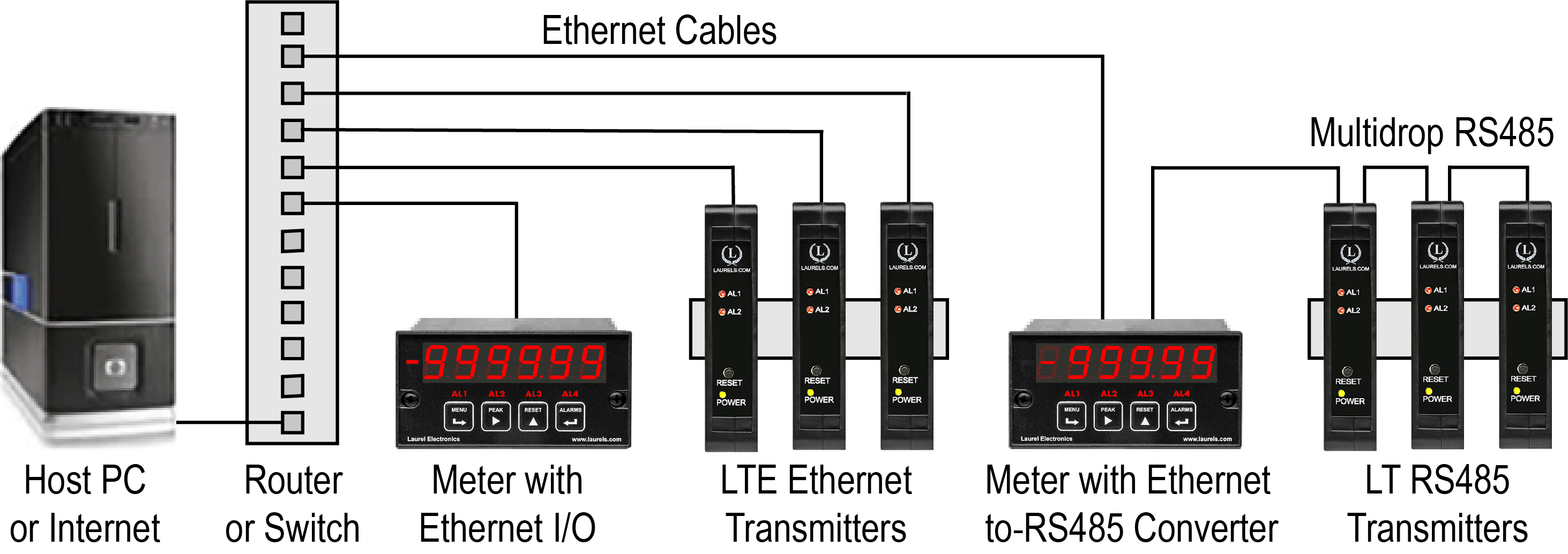
Connecting Laureate LTE Transmitters to a Local Area Network (LAN)
Laurel LTE series Ethernet transmitters can connect directly to a LAN via an Ethernet cable. Up to 30 Laureate LT Transmitters and/or Digital Panel Meters can be configured for RS485 and daisy-chained to an LT Transmitter for seamless LAN integration. Setup for both configurations is streamlined using Laurel’s free Instrument Setup Software, which simplifies node discovery and transmitter configuration.
Flexible Communication Options for LTE Transmitters
Laureate Transmitters can be equipped with Laurel communication boards to support various interfaces and protocols. These include serial interfaces with ASCII or Modbus RTU protocols, and Ethernet interfaces with web access, ASCII, or Modbus TCP/IP protocols, ensuring versatile connectivity for your commercial applications.
| LTE Transmitter Signal Input & Function | Model Series | Analog Output | Ethernet I/O | Dual Relays | |
|---|---|---|---|---|---|
| 1 | DC Input Voltage and Current | LTE-DC |  |
 |
 |
| 2 | AC RMS Voltage or Current | LTE-RMS |  |
 |
 |
| 3 | Process Voltage or Current | LTE-P |  |
 |
 |
| 4 | Strain Gauge or Potentiometer Follower | LTE-SG |  |
 |
 |
| 5 | Weighing Applications | LTE-WA |  |
 |
 |
| 6 | Load Cell & Microvolt Signals | LTE-WM |  |
 |
 |
| 7 | Thermocouple (Types J, K, T, E, N, R, S) | LTE-TC |  |
 |
 |
| 8 | RTD Temperature | LTE-RTD |  |
 |
 |
| 9 | Resistance in Ohms | LTE-R |  |
 |
 |
| 10 | Frequency, Rate, Speed | LTE-FR |  |
 |
 |
| 11 | Pulse Input Totalizer | LTE-FR |  |
 |
 |
| 12 | Process Signal Totalizer | LTE-VF |  |
 |
 |
| 13 | Batch Controller Analog Input | LTE-FR |  |
 |
 |
| 14 | Batch Controller Pulse Input | LTE-FR |  |
 |
 |
| 15 | Sum, Difference, Ratio, Product of 2 Inputs | LTE-FR |  |
 |
 |
| 16 | On/Off Duty Cycle | LTE-FR |  |
 |
 |
| 17 | Stopwatch Timing for Single Events | LTE-FR |  |
 |
 |
| 18 | Average Time of Periodic Events | LTE-FR |  |
 |
 |
| 19 | AC Phase Angle and Power Factor | LTE-FR |  |
 |
 |
| 20 | Quadrature Position or Rate | LTE-QD |  |
 |
 |
Laureate™ Ethernet & 4-20 mA Output Transmitter for Ratio, Product, Sum or Difference of Two Inputs
| Pulse Inputs | ||||
|---|---|---|---|---|
| Signal Types | AC, pulses from NPN, PNP transistors, contacts, magnetic pickups | |||
| Signal Ground | Common ground for channels A & B. | |||
| Channel A Frequency | 0.005 Hz to 1 MHz | |||
| Channel B Frequency | 0.005 Hz to 250 kHz | |||
| Minimum Signal | Nine ranges from (-12 to +12 mV) to (+1.25 to +2.1V) | |||
| Maximum Signal | 250 Vac | |||
| Noise Filter | 1 MHz, 30 kHz, 250 Hz (selectable) | |||
| Contact Debounce | 0, 3, 50 ms (selectable) | |||
| Time Base Accuracy | Quartz crystal calibrated to ±2 ppm | |||
| Arithmetic Functions | A+B, A-B, AxB, A/B, A/B-1 | |||
| Recalibration: All ranges are calibrated at the factory. Recalibration is recommended every 12 months. | ||||
| Analog Output (standard) | ||||
| Output Levels | 4-20 mA and 0-10 Vdc (selectable) | |||
| Compliance, 4-20 mA | 10V (0-500Ω load) | |||
| Compliance, 0-10V | 2 mA (5 kΩ load) | |||
| Output Resolution | 16 bits (65,536 steps) | |||
| Output Accuracy | ±0.02% of output span | |||
| Output Update Rate | Programmed gate time + 30 ms + 0-2 signal periods | |||
| Output Isolation | 250V rms working, 2.3 kV rms per 1 minute test | |||
| Ethernet Data I/O (standard) | ||||
| Type | 10/100 Base-T Ethernet per IEEE 802.3 | |||
| Data Rates | 300, 600, 1200, 2400, 4800, 9600, 19200 baud | |||
| Output Isolation | 250V rms working, 2.3 kV rms per 1 min test | |||
| Serial Protocol | Modbus TCP | |||
| Modbus Compliance | Modbus over Serial Line Specification V1.0 (2002) | |||
| Digital Addresses | 247 | |||
| Dual Relay Output (standard) | ||||
| Relay Type | Two solid state relays, SPST, normally open, Form A | |||
| Load Rating | 120 mA at 140 Vac or 180 Vdc | |||
| Excitation Output (standard) | ||||
| 5 Vdc | 5 Vdc ± 5%, 100 mA (jumper selectable) | |||
| 10 Vdc | 10 Vdc ± 5%, 120 mA (jumper selectable) | |||
| 12 Vdc | 12 Vdc ± 5%, 100 mA (jumper selectable) | |||
| 24 Vdc | 24 Vdc ± 5%, 50 mA (jumper selectable) | |||
| Output Isolation | 50 Vdc from signal ground | |||
| Power Input | ||||
| Standard Power | 85-264 Vac or 90-300 Vdc | |||
| Low Power Option | 10-48 Vdc or 12-32 Vac | |||
| Power Frequency | DC or 47-63 Hz | |||
| Power Isolation | 250V rms working, 2.3 kV rms per 1 min test | |||
| Power Consumption | 2.5W typical at 24V, 4.0W with max excitation output | |||
| Environmental | ||||
| Operating Temperature | -40°C to 70°C (-40°F to 158°F) | |||
| Storage Temperature | -40°C to 85°C (-40°F to 185°F) | |||
| Relative Humidity | 95% at 40°C, non-condensing | |||
| Cooling Required | Mount transmitters with ventilation holes at top and bottom. Leave 6 mm (1/4") between transmitters, or force air with a fan. | |||
| Mechanical | ||||
| Enclosure | Rugged black polycarbonate housing material | |||
| Mounting | 35 mm rail per DIN EN 50022 | |||
| Dimensions | 129 x 104 x 22.5 mm case | |||
| Connectors | Detachable screw clamp connectors meet VDE / IEC / UL / CSA standards. RJ45 jack for Ethernet | |||
| Tightening Torque | Screw terminal connectors: 5 lb-in (0.56 Nm) | |||
| Weight | Complete transmitter: 183 g (6.5 oz) | |||
| Replacement Case Screws | ||||
| Size | 6 | |||
| Thread Pitch | 6-19 | |||
| Length | 1/2" | |||
| Head Style | Pan Head | |||
| Drive Style | Phillips | |||
| Head Diameter | 0.256-0.270 | |||
| Head Height | 0.087-0.097 | |||
| Full/Partial Thread | Full | |||
| Drive Size | 2 | |||
| Material | Steel | |||
| Finished | Black Oxide | |||
| General | ||||
| Programming | Utilize Laurel's free Instrument Setup Software, which runs on a PC under MS Windows. | |||
| Security | Lockout options available using Laurel's free Instrument Setup Software. | |||
| Warranty | 3 years parts & labor | |||
| Recalibration: All ranges are calibrated at the factory. Recalibration is recommended every 12 months. | ||||
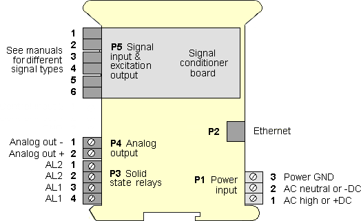
Transmitter Pinout
Free Instrument Setup Software for Series 2 Laureates
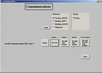
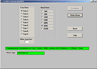
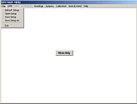
Free Downloadable Windows-based Instrument Setup (IS) software (Data Interface Board Required) for use with our programmable Digital Panel Meters, Scale Meters, Counters, Timers, Remote Displays, and Transmitters, are an easy method to set up Laureate 1/8 DIN digital panel meters, counters, timers, remote displays, and DIN-rail transmitters, as explained in the Instrument Setup Software Manual. Laureate 1/8 DIN instruments can also be set up from the front panel, as explained in their respective Owners Manuals. Instrument Setup software is of benefit whether or not the PC is connected to the instrument.
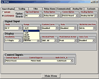
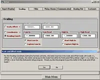
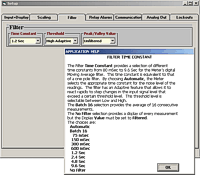
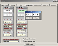
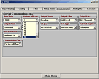
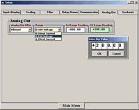
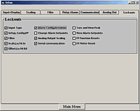
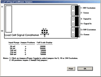
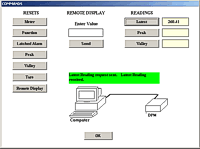
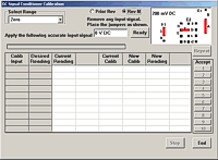
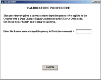
- When the PC is connected to the instrument, Instrument Setup software can retrieve the setup file from the instrument or open a default setup file or previously saved setup file from disk View Setup, then provides graphical user interface (GUI) screens with pull-down menus applicable to input, display, scaling, filtering, alarms, communications, analog output, and front panel lockouts. Fields that are not applicable to the instrument as configured are either left out or grayed out. Clicking on any item will bring up a detailed Help screen for that item. After editing, the setup file can be downloaded, uploaded to the instrument, or saved to a disk. The same setup file can then be downloaded into multiple instruments.
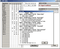
- When the PC is not connected to the instrument, the above GUI screens can be used to set up a virtual instrument. The setup file can then be saved to disk. Switching toView Menu then brings up a screen with the required front panel programming steps. This view can be printed out for use at the instrument site and to serve as a hard copy record.
Download Free Instrument Setup Software
Installation
Set User Account Control (UAC) of MS Windows to "Never notifiy me" so that Instrument Setup Software can create directories. The UAC change screen can be reached as follows:
- Under Windows 7, click on the Windows Start button in the lower left of the desktop and enter "UAC" in the search field.
- Under Windows 8, navigate to Control Panel, then to the "User Accounts and Family Safety" section, and click on "Change User Account Control Settings."
- Under Windows 10, click on the Windows Start button in the lower left of the desktop, then on "Settings", and enter "UAC" in the search field.
- Reboot your computer for the changed UAC setting to take effect.

RJ11-to-DB9 cable with rear view of DB9 connector to PC
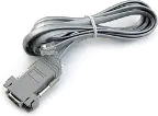
RS232 cable, meter to PC, P/N CBL01
Laureate 1/8 DIN Laureate instruments must be equipped with a serial communications board and be connected to the computer via a serial communications cable. The connection can be via RS232, RS485, USB or Ethernet. Following setup, the serial communications board may be removed from the instrument if desired. The wiring of the RS232 cable is illustrated above with end views of the two connectors.
Laureate LT Series transmitters come standard with a 3-wire serial interface, which can be jumpered for RS232 or RS485.
Laureate LTE Series transmitters come standard with an Ethernet interface.
Meter Setup Screens
Click on any of the reduced screens below for a full-size screen view, then click on the Back button of your browser to return to this page. The screens examples below are for a fully-loaded Series 2 Digital Panel Meter (DPM), which is connected to the PC via RS232. If the meter is a Series 1 meter (pre-2007), this is sensed by the software, and somewhat different screens are brought up. Please see Series 1 setup screens.


Meter Setup Utilities


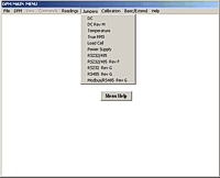
From the Main Menu, click on Readings if your PC is connected to the meter. A pull-down menu then offers three choices: List, Plot and Graph.
- List presents the latest readings in a 20-row by 10-column table. Press Pause at any time to freeze the display. This is one method to capture peak readings.
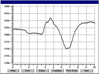
- Plot generates a plot of readings vs. time in seconds. It effectively turns the DPM-PC combination into a printing digital oscilloscope.

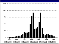
- Graph generates a histogram where the horizontal axis is the reading and the vertical axis is the number of occurrences of readings. The display continually resizes itself as the number of readings increases.


Dimensions
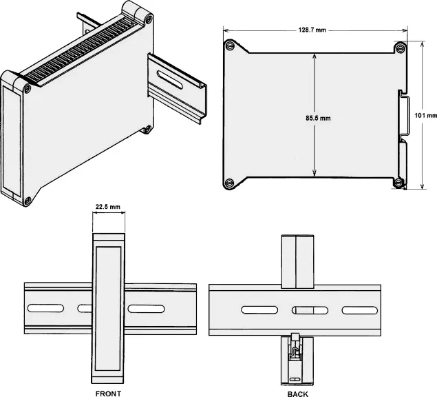
Dimensioned CAD assembly drawings in EPRT, STEP, x_t, .dwg, pdf file formats: Laureate-transmitter-case.zip (zipping prevents browser from opening CAD files as text files).
| Controlling the Mixing Ratio of Two Fluids | |
|---|---|
 |
Transmitting and alarming the input flow rate ratio of two fluids (gas or liquid) allows these to be mixed in a predetermined ratio in continuous processes. The sensing element is normally a turbine flow meter, which outputs pulses at a frequency proportional to flow rate. The A/B ratio can also be transmitted for totalized rate (or delivered volume). |
| Comparing Fluid Inflow & Outflow | |
 |
The ratio of the inflow and outflow rates of a tank is a measure of the relative filling or emptying rate. The same transmitter can also be programmed to transmit the net inflow or outflow rate in flow units, or to transmit totalized inflow our outflow in volume units. Any of these parameters can be alarmed using the dual relay board and be transmitted via 4-20 mA. |
| Controlling Coating Thickness on a Film | |
 |
In this application, Channel A measures the rate at which a coating material is applied, as measured by a flow meter, while Channel B measures the speed of the film based on pulses from a proximity switch. Transmitting and alarming the A/B ratio assures that an even thickness of coating material is applied as the speed of the film is varies. |
| Instrumenting a Pulsed Laser System | |
 |
The dual-channel Laureate transmitter can measure the speed of conveyor lines by using the output of proximity switches which sense gear teeth or spokes of rotating drive wheels. Transmitting the speed ratio of two lines allows line speeds to be adjusted so that material arrives at work stations when needed. |
| Measuring Draw for Elongation | |
 |
Draw (Ch A / Ch B - 1) can be used to indicate the elongation of films compressed between rollers, the shrinkage films, and the RPM difference of rollers whose speed is varied to maintain tension. The high resolution of Laureate dual channel transmitters is ideal for comparison of rates that are close to each other. |
CAL-Digital
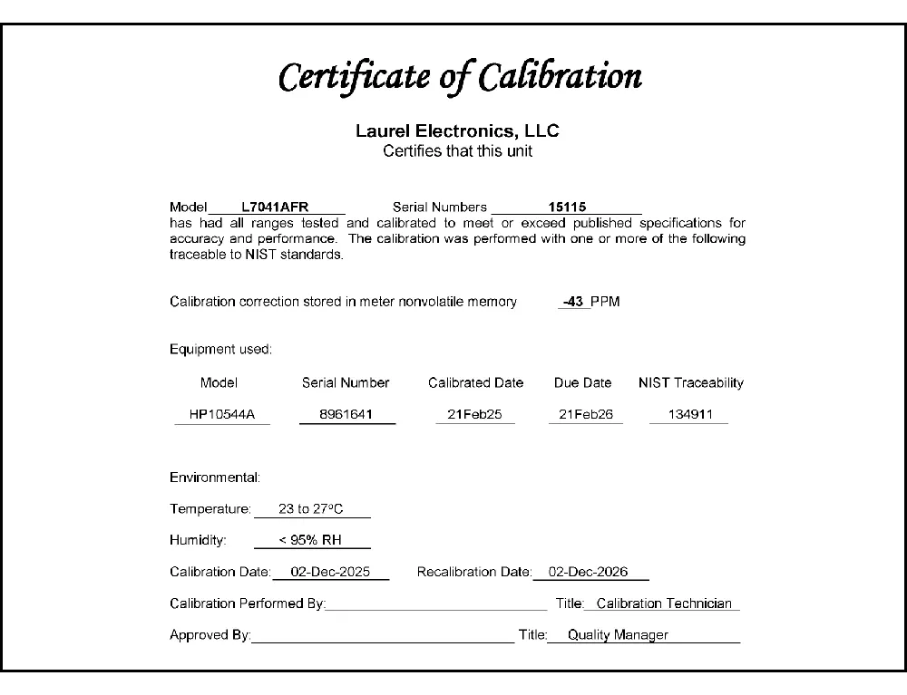
Certificate of Calibration
$65.00CBL02
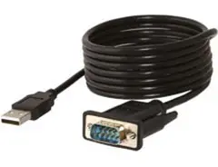
USB-to-RS232 Adapter Cable
$47.00CBL04
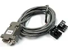
RS232 Cable for LT Transmitters
$47.00Understanding LTE DIN Rail Digital Transmitters: Ethernet Communication and Analog Outputs for Complex Ratio Calculations
In industrial and automation environments, precise measurement and control of various parameters are crucial for optimal performance and efficiency. One of the key components that aid in these tasks is the DIN rail digital transmitter, specifically the LTE Series with Ethernet communication and analog outputs. This article explores the features and applications of this advanced transmitter, focusing on its ability to handle complex ratio, product, sum, or difference calculations of two rates or totals.
What is an LTE DIN Rail Digital Transmitter?
The LTE Series DIN Rail Digital Transmitter is a sophisticated device designed for industrial control systems. Its primary function is to convert various process signals into standardized outputs for further processing or monitoring. The transmitter is designed to be mounted on a DIN rail, a common standard for mounting electrical and industrial equipment, ensuring easy installation and integration within existing systems.
Key Features
-
Ethernet Communication: The LTE Series transmitter comes equipped with Ethernet communication capabilities, allowing it to integrate seamlessly into modern networked control systems. This feature enables real-time data transmission, remote monitoring, and configuration via standard network protocols. Ethernet communication enhances data accessibility and facilitates advanced network management and diagnostics.
-
Analog Outputs: One of the standout features of the LTE Series transmitter is its provision of analog outputs. These outputs can represent various calculated values such as ratio, product, sum, or difference of two rates or totals. The analog outputs are crucial for interfacing with other control systems or instruments that require continuous signal representation.
-
Ratio, Product, Sum, or Difference Calculations: The LTE Series transmitter is designed to handle complex calculations involving two input rates or totals. This capability allows it to perform:
- Ratio Calculations: Determining the proportional relationship between two values, which is essential for processes that depend on the relative proportion of inputs.
- Product Calculations: Multiplying two input values to obtain a result that can be used for further analysis or control.
- Sum Calculations: Adding two input values to provide a cumulative total, useful in applications where combined values are required.
- Difference Calculations: Subtracting one input value from another to monitor deviations or changes between two parameters.
Applications
-
Process Control: In industrial process control, precise measurement and control are essential. The LTE Series transmitter’s ability to calculate ratios, products, sums, and differences allows for accurate control of processes such as mixing, blending, and flow measurement.
-
Energy Management: For energy management systems, the transmitter can calculate the ratio of energy consumption or the sum of energy totals across different sections of a facility. This information is critical for optimizing energy use and reducing costs.
-
Manufacturing: In manufacturing environments, the transmitter's capability to handle complex calculations supports various applications, including production monitoring, quality control, and equipment performance analysis.
-
Data Logging and Analysis: With its Ethernet communication feature, the LTE Series transmitter can integrate with data logging systems to provide real-time data for analysis. This integration facilitates trend analysis and predictive maintenance.
Conclusion
The LTE DIN Rail Digital Transmitter stands out as a versatile and powerful tool in industrial measurement and control systems. Its advanced features, including Ethernet communication and the ability to perform complex ratio, product, sum, or difference calculations, make it an invaluable asset for a wide range of applications. By providing accurate and real-time data, the LTE Series transmitter supports efficient process control, effective energy management, and improved manufacturing operations, ultimately contributing to enhanced productivity and operational excellence.
Applications of LTE DIN Rail Digital Transmitter with Ethernet Communication and Analog outputs for Ratio, Product, Sum or Difference of 2 Rates or Totals
In industrial automation and control systems, precision and versatility are critical. The LTE Series DIN Rail Digital Transmitter with Ethernet communication and analog outputs stands out as a vital component in various applications. This article explores where such a transmitter is used, highlighting its role in measuring and managing multiple rates or totals.
1. Industrial Process Control
In industrial settings, managing and monitoring multiple processes simultaneously is essential. The LTE Series DIN Rail Digital Transmitter excels in environments where precise measurement of flow rates, pressures, or temperatures is required. For example, in a chemical processing plant, the transmitter can be used to measure and control the ratio of two different chemical flows, ensuring that the final product meets specific quality standards. By providing analog outputs for the ratio, product, sum, or difference of these rates or totals, the transmitter allows for real-time adjustments and control.
2. Building Management Systems (BMS)
Building Management Systems require accurate monitoring of various parameters such as energy consumption, HVAC system performance, and water usage. The LTE Series transmitter's ability to handle multiple inputs and outputs makes it ideal for integrating into BMS. For instance, it can be used to monitor the total energy consumption of different building sections and provide a sum or difference of these totals for efficient energy management. The Ethernet communication capability allows for easy integration with the BMS network, enabling centralized monitoring and control.
3. Water and Wastewater Treatment
Water and wastewater treatment facilities rely heavily on accurate measurement and control of various flow rates and chemical dosages. The LTE Series transmitter can measure the ratio of influent to effluent flows, ensuring optimal treatment processes. Additionally, it can handle the sum of flow rates from different treatment stages or the difference between inflow and outflow rates, aiding in effective management and operational efficiency. The Ethernet communication feature facilitates remote monitoring and data analysis, improving overall system management.
4. Oil and Gas Industry
In the oil and gas sector, the LTE Series DIN Rail Digital Transmitter is used to monitor and control the flow of different fluids and gases. Its ability to measure and output ratios, products, sums, or differences of rates or totals is crucial for optimizing production and ensuring safety. For example, it can be used to balance the flow rates of various components in a refinery or monitor the total output from different production units. The Ethernet communication allows for integration with SCADA systems, enhancing data accessibility and control.
5. Manufacturing and Production
Manufacturing facilities often require precise control of material inputs and outputs to ensure product consistency and quality. The LTE Series transmitter can measure the ratio of different raw materials fed into a production line or the sum of output from multiple machines. By providing real-time data through analog outputs, it supports automated adjustments and enhances process efficiency. The Ethernet communication capability enables seamless integration with manufacturing execution systems (MES) for improved process monitoring and control.
Conclusion
The LTE Series DIN Rail Digital Transmitter with Ethernet communication and analog outputs is a versatile tool used across various industries for precise measurement and control of multiple rates or totals. Its applications in industrial process control, building management systems, water and wastewater treatment, oil and gas, and manufacturing underscore its importance in optimizing operations and ensuring efficiency. By offering real-time data and integration capabilities, it plays a crucial role in modern automation and control systems.
Less Information.


