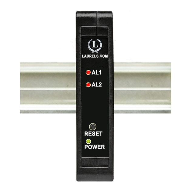
New Front Panel USB-C Port Coming Soon!
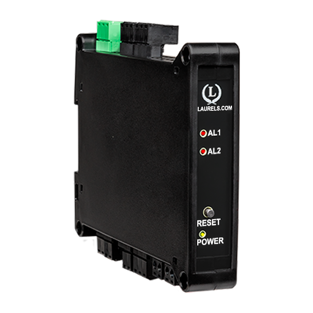
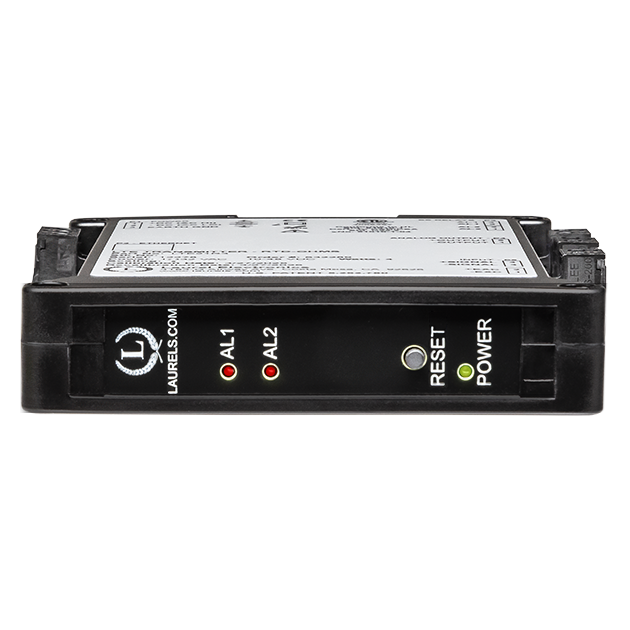
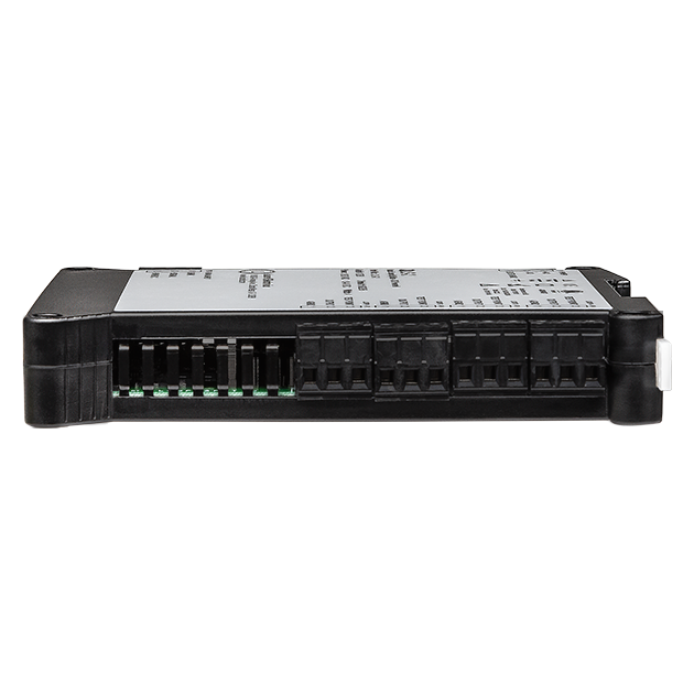
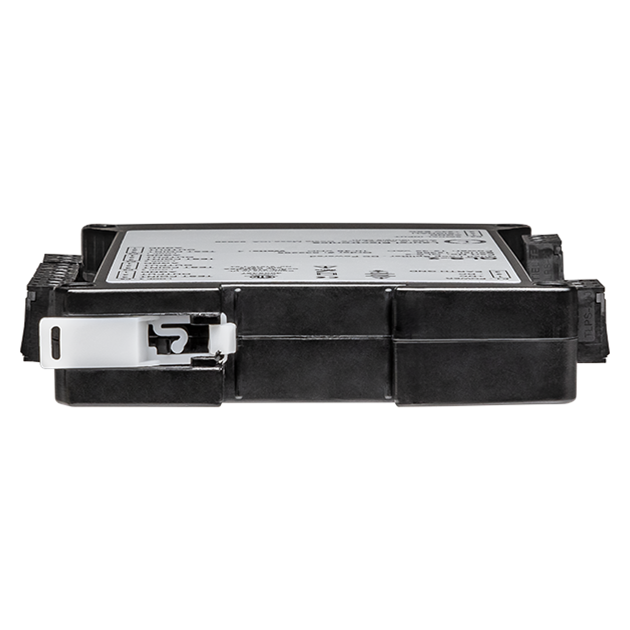
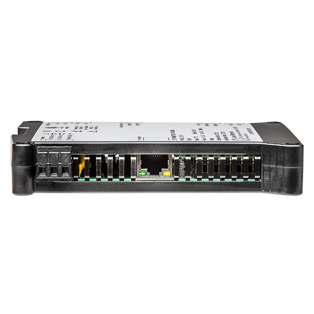
The Laureate 4-20 mA, 0-20 mA, 0-10V or -10V to +10V and ethernet output transmitter for RTD temperature offers the same high performance, signal conditioning and programmable features as Laureate digital panel meters, counters & timers provides six voltage input ranges and four current input ranges, all factory calibrated and jumper selectable. The temperature transmitter provides a linearized, highly accurate, stable and repeatable transmitter output for 100 ohm platinum, 10 ohm copper and 120 ohm nickel RTDs. Pt100 platinum RTDs can have a DIN alpha of 0.00385 or ANSI alpha of 0.00392. The RTD type and temperature range, specified in °C or °F, are user-selectable. The temperature range can be as wide as the entire span of the RTD type or as narrow as 150 counts (such as 15.0°), limited only by considerations of electrical noise and digital filtering time constants.
RTD connections can be via 2, 3 or 4 wires. With 3 or 4-wire connections, the transmitter automatically compensates for changes in lead resistance to the sensor. With 2-wire connection, the transmitter can measure and then subtract the lead wire resistance.
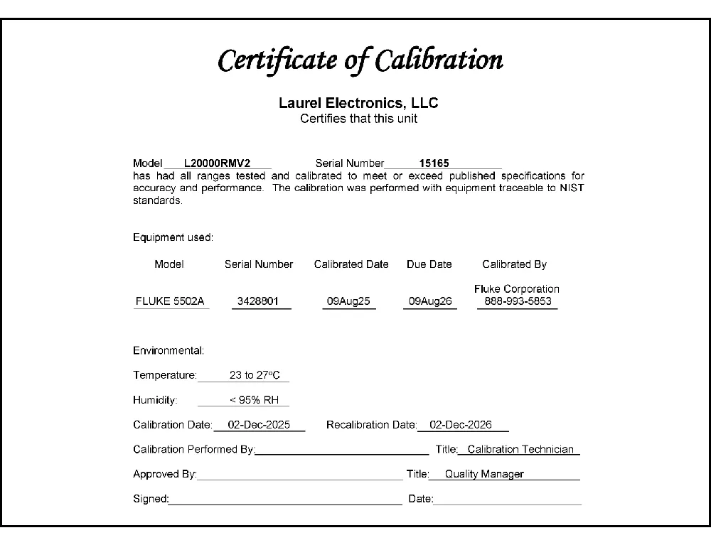
All RTD types are factory-calibrated, with calibration factors for each range securely stored in an onboard EEPROM. These factors can be scaled via software to accommodate external shunts, enabling field replacement of signal conditioner boards without necessitating recalibration of the associated transmitter. For optimal accuracy, factory recalibration is recommended annually. All Laurel Electronics instruments undergo factory calibration using the industry-leading Fluke calibrators, which are recalibrated yearly and certified traceable to national standards, ensuring the highest level of precision and reliability.
Calibration data is stored in EEPROM on the signal conditioner board. This allows signal conditioner boards and ranges to be changed in the field with no need for recalibration. Typical accuracy for a Pt100 is better than ±0.04°C (±0.07°F) ±0.01% of reading. Open sensor indication is standard and may be set up to indicate either upscale or downscale. RTD excitation is provided by the transmitter. RTD connections can be of the 2-, 3- or 4-wire type. With 3- and 4-wire connections, the transmitter automatically compensates for changes in lead resistance to the sensor. Instrument Setup Software allows user calibration for RTDs whose resistance is different than nominal at 0°C.
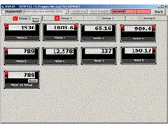
Easy USB-C Programming: Configure Laureate transmitters through the front-panel USB-C port with Laurel’s free Instrument Setup Software for Windows. Configurations can be saved to the transmitter, a PC, a file server, or a USB thumb drive. Laurel’s free Instrument Setup Software can also be used for light-duty data collection.
High read rate of up to 50 or 60 conversions per second, the Laureate™ LTE Series transmitter uses Concurrent Slope (US Pat. 5,262,780) analog-to-digital conversion to integrate signals over a full power line cycle (50 Hz or 60 Hz). This read rate enables peak and valley capture, real-time computer interfacing, and control applications. Peak and valley values are automatically captured and can be viewed using Laurel’s free Instrument Setup Software (compatible with Windows PCs) or transmitted as serial data.
Two tare functions: auto-tare and manual tare. In auto-tare, an input line is grounded by an external pushbutton. This causes the current weight, which is normally the empty weight of the container to be stored in memory as an offset. In manual tare, the tare value can be entered manually via a control input pushbutton or using Laurel's free Instrument Setup Software.
Peak and valley values are automatically captured. These may be displayed via Laurel's free Instrument Setup Software, which runs on a PC under MS Windows or can be transmitted as serial data.

LTE series DIN rail transmitters & signal conditioners can be interfaced to a wide range of sensors and transducers using one of seven available plug-in signal conditioner boards. The transmitters duplicate the high performance (high accuracy, high read rate) and extensive programmable features of Laureate 1/8 DIN digital panel meters, counters and timers. They utilize the same signal conditioners boards, much of the same firmware, and Laurel's free Windows-based Instrument Setup Software. They come in a compact DIN rail mount package with detachable screw-clamp connectors for easy wiring.
The LTE series Transmitters accessible from this page include a 4-20 mA, 0-20 mA, 0-10V, or -10V to +10V analog output (isolated, user selectable), an ethernet serial data interface (isolated, user selectable), and dual 120 mA solid state AC/DC relays (isolated). An (isolated) 5, 10, 12, or 24 Vdc transducer excitation output is included with all models other than those with a temperature or AC RMS signal conditioner.
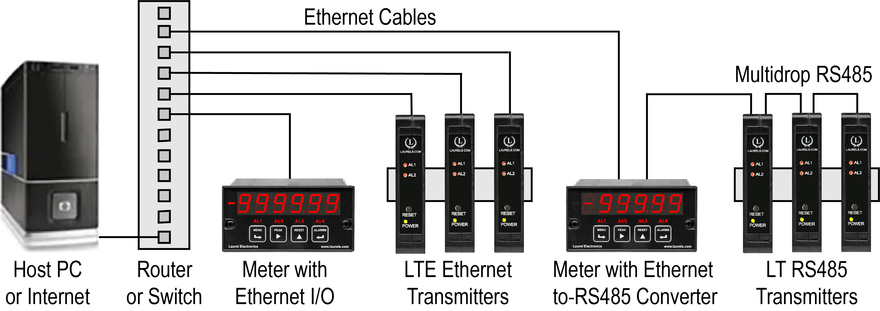
Laurel LTE series Ethernet transmitters can connect directly to a LAN via an Ethernet cable. Up to 30 Laureate LT Transmitters and/or Digital Panel Meters can be configured for RS485 and daisy-chained to an LT Transmitter for seamless LAN integration. Setup for both configurations is streamlined using Laurel’s free Instrument Setup Software, which simplifies node discovery and transmitter configuration.
Laureate Transmitters can be equipped with Laurel communication boards to support various interfaces and protocols. These include serial interfaces with ASCII or Modbus RTU protocols, and Ethernet interfaces with web access, ASCII, or Modbus TCP/IP protocols, ensuring versatile connectivity for your commercial applications.
| LTE Transmitter Signal Input & Function | Model Series | Analog Output | Ethernet I/O | Dual Relays | |
|---|---|---|---|---|---|
| 1 | DC Input Voltage and Current | LTE-DC |  |
|
|
| 2 | AC RMS Voltage or Current | LTE-RMS | |
|
|
| 3 | Process Voltage or Current | LTE-P | |
|
|
| 4 | Strain Gauge or Potentiometer Follower | LTE-SG | |
|
|
| 5 | Weighing Applications | LTE-WA | |
|
|
| 6 | Load Cell & Microvolt Signals | LTE-WM | |
|
|
| 7 | Thermocouple (Types J, K, T, E, N, R, S) | LTE-TC | |
|
|
| 8 | RTD Temperature | LTE-RTD | |
|
|
| 9 | Resistance in Ohms | LTE-R | |
|
|
| 10 | Frequency, Rate, Speed | LTE-FR | |
|
|
| 11 | Pulse Input Totalizer | LTE-FR | |
|
|
| 12 | Process Signal Totalizer | LTE-VF | |
|
|
| 13 | Batch Controller Analog Input | LTE-FR | |
|
|
| 14 | Batch Controller Pulse Input | LTE-FR | |
|
|
| 15 | Sum, Difference, Ratio, Product of 2 Inputs | LTE-FR | |
|
|
| 16 | On/Off Duty Cycle | LTE-FR | |
|
|
| 17 | Stopwatch Timing for Single Events | LTE-FR | |
|
|
| 18 | Average Time of Periodic Events | LTE-FR | |
|
|
| 19 | AC Phase Angle and Power Factor | LTE-FR | |
|
|
| 20 | Quadrature Position or Rate | LTE-QD | |
|
|
| RTD Metal | Alpha | R at 0°C | R at top of range |
Excitation Current |
Range | Max Error |
|---|---|---|---|---|---|---|
| Platinum Pt100 |
0.003850 (DIN) | 100Ω | 390.48Ω at 850°C |
196 µA | -202°C to +850°C -331°F to +1562°F |
±0.03°C ±0.01% of rdg ±0.05°F ±0.01% of rdg |
| Platinum Pt100 |
0.003902 (ANSI) | 100Ω | 394.36Ω at 850°C |
196 µA | -202°C to +850°C -331°F to +1168°F |
±0.04°C ±0.01% of rdg ±0.07°F ±0.01% of rdg |
| Nickel Ni120 |
0.00672 | 120Ω | 380.31Ω at 260°C |
196 µA | -80°C to +260°C -112°F to +500°F |
±0.05°C ±0.01% of rdg ±0.09°F ±0.01% of rdg |
| Copper Cu10 |
0.00427 | 9.035Ω | 19.116Ω at 260°C |
5.0 mA | -100°C to +260°C -148°F to +500°F |
±0.05°C ±0.01% of rdg ±0.09°F ±0.01% of rdg |
| Recalibration: All ranges are calibrated at the factory. Recalibration is recommended every 12 months. | ||||||
| RTD Input | ||||
|---|---|---|---|---|
| Calibration, Pt 100 DIN | IEC 751 (IPTS-68) | |||
| Calibration, Pt 100 ANSI | NIST Monograph 126 | |||
| Configuration | 2, 3 or 4-wire connection | |||
| Excitation current | 0.2 mA | |||
| Max error at 25°C, Pt100 | ±0.04°C (±0.07°F) ±0.01% of reading | |||
| Span tempco | ±0.003% of reading/°C | |||
| Zero tempco | ±0.03 deg/deg | |||
| Sensor lead resistance | 2-wire: 10 mdeg/Ω/deg up to 10Ω; | |||
| tempco per conductor | 3 & 4-wire: 10 μdeg/Ω/deg up to 100Ω | |||
| Over-voltage protection | 125 Vac | |||
| Open sensor indication | 0 mA or > 20 mA output, selectable | |||
| Provision for user calibration | Multiplier of RTD resistance plus offset in degrees | |||
| Analog Output (standard) | ||||
| Output Levels | 4-20 mA and 0-10 Vdc (selectable) | |||
| Compliance, 4-20 mA | 10V (0-500Ω load) | |||
| Compliance, 0-10V | 2 mA (5 kΩ load) | |||
| Output Resolution | 16 bits (65,536 steps) | |||
| Output Accuracy | ±0.02% of output span | |||
| Output Isolation | 250V rms working, 2.3 kV rms per 1 minute test | |||
| Step response time | 50 ms | |||
| Ethernet Data I/O (standard) | ||||
| Type | 10/100Base-T Ethernet per IEEE 802.3 | |||
| Data Rates | 300, 600, 1200, 2400, 4800, 9600, 19200 baud | |||
| Output Isolation | 250V rms working, 2.3 kV rms per 1 min test | |||
| Serial Protocol | Modbus TCP | |||
| Modbus Compliance | Modbus over Serial Line Specification V1.0 (2002) | |||
| Digital Addresses | 247 for Modbus | |||
| Dual Relay Output (standard) | ||||
| Relay Type | Two solid state relays, SPST, normally open, Form A | |||
| Load Rating | 120 mA at 140 Vac or 180 Vdc | |||
| Power Input | ||||
| Standard Power | 85-264 Vac or 90-300 Vdc | |||
| Low Power Option | 10-48 Vdc or 12-32 Vac | |||
| Power Frequency | DC or 47-63 Hz | |||
| Power Isolation | 250V rms working, 2.3 kV rms per 1 min test | |||
| Power Consumption | 2.5W typical at 24V | |||
| Environmental | ||||
| Operating Temperature | -40°C to 70°C (-40°F to 158°F) | |||
| Storage Temperature | -40°C to 85°C (-40°F to 185°F) | |||
| Relative Humidity | 95% at 40°C, non-condensing | |||
| Cooling Required | Mount transmitters with ventilation holes at top and bottom. Leave 6 mm (1/4") between transmitters, or force air with a fan. | |||
| Mechanical | ||||
| Enclosure | Rugged black polycarbonate housing material | |||
| Mounting | 35 mm rail per DIN EN 50022 | |||
| Dimensions | 129 x 104 x 22.5 mm case | |||
| Connectors | Detachable screw clamp connectors meet VDE / IEC / UL / CSA standards. RJ45 jack for Ethernet | |||
| Tightening Torque | Screw terminal connectors: 5 lb-in (0.56 Nm) | |||
| Weight | Complete transmitter: 183 g (6.5 oz) | |||
| Replacement Case Screws | ||||
| Size | 6 | |||
| Thread Pitch | 6-19 | |||
| Length | 1/2" | |||
| Head Style | Pan Head | |||
| Drive Style | Phillips | |||
| Head Diameter | 0.256-0.270 | |||
| Head Height | 0.087-0.097 | |||
| Full/Partial Thread | Full | |||
| Drive Size | 2 | |||
| Material | Steel | |||
| Finished | Black Oxide | |||
| General | ||||
| Front-Panel Port | USB-C (programming & data) | |||
| Programming | Utilize Laurel's free Instrument Setup Software, which runs on a PC under MS Windows | |||
| Security | Lockout options available using Laurel's free Instrument Setup Software | |||
| Warranty | 3 years parts & labor | |||
| Recalibration: All ranges are calibrated at the factory. Recalibration is recommended every 12 months. | ||||
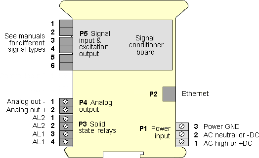
RTD hookup can be via 2, 3 or 4 wires to the J5 connector. The transmitter applies an excitation current of 196 µA (Pt 100 and Ni 120) or 5 mA (Cu 10).
 |
In 4-wire hookup, different pairs of leads are used to apply the excitation current and sense the voltage drop across the RTD, so that the IR drop across the excitation leads is not a factor. |
 |
In 3-wire hookup, the transmitter senses the combined voltage drop across the RTD plus two excitation leads. It also senses the voltage drop across one excitation lead, and then subtracts twice this voltage from the combined total. This technique effectively subtracts all lead resistance and compensates for ambient temperature changes if the two excitation leads are identical. |
 |
In 2-wire hookup, the transmitter senses the combined voltage drop across the RTD and both lead wires. The voltage drop across the lead wires can be measured by shorting out the RTD during transmitter setup, and this voltage is then automatically subtracted from the combined total. However, changing resistance of the lead wires due to ambient temperature changes will not be compensated. |
|
|
| 1/8 DIN Digital Panel Meters | DIN Rail Transmitters |
Free Downloadable Windows-based Instrument Setup (IS) software (Data Interface Board Required) for use with our programmable Digital Panel Meters, Scale Meters, Counters, Timers, Remote Displays, and Transmitters, are an easy method to set up Laureate 1/8 DIN digital panel meters, counters, timers, remote displays, and DIN-rail transmitters, as explained in the Instrument Setup Software Manual. Laureate 1/8 DIN instruments can also be set up from the front panel, as explained in their respective Owners Manuals. Instrument Setup software is of benefit whether or not the PC is connected to the instrument.
Set User Account Control (UAC) of MS Windows to "Never notifiy me" so that Instrument Setup Software can create directories. The UAC change screen can be reached as follows:
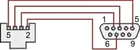
RJ11-to-DB9 cable with rear view of DB9 connector to PC
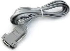
RS232 cable, meter to PC, P/N CBL01
Laureate 1/8 DIN Laureate instruments must be equipped with a serial communications board and be connected to the computer via a serial communications cable. The connection can be via RS232, RS485, USB or Ethernet. Following setup, the serial communications board may be removed from the instrument if desired. The wiring of the RS232 cable is illustrated above with end views of the two connectors.
Laureate LT Series transmitters come standard with a 3-wire serial interface, which can be jumpered for RS232 or RS485.
Laureate LTE Series transmitters come standard with an Ethernet interface.
Click on any of the reduced screens below for a full-size screen view, then click on the Back button of your browser to return to this page. The screens examples below are for a fully-loaded Series 2 Digital Panel Meter (DPM), which is connected to the PC via RS232. If the meter is a Series 1 meter (pre-2007), this is sensed by the software, and somewhat different screens are brought up. Please see Series 1 setup screens.


From the Main Menu, click on Readings if your PC is connected to the meter. A pull-down menu then offers three choices: List, Plot and Graph.


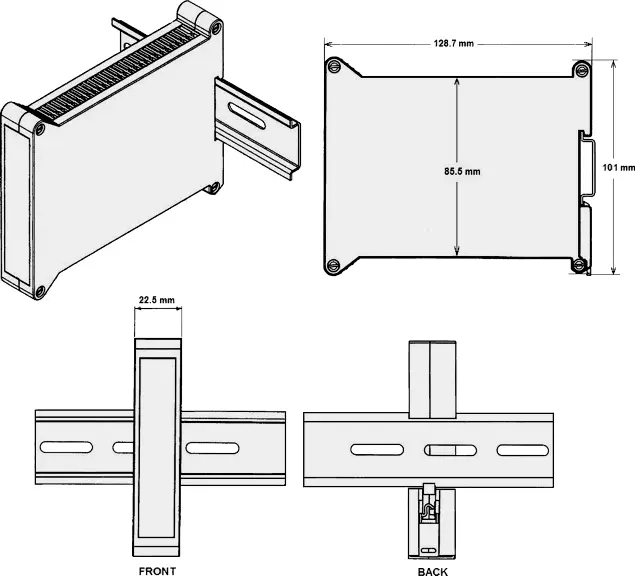
Dimensioned CAD assembly drawings in EPRT, STEP, x_t, .dwg, pdf file formats: Laureate-transmitter-case.zip (zipping prevents browser from opening CAD files as text files).
CAL-Analog
Certificate of Calibration
$65.00DLS-XLOG2
XLog2 Data logging Software
$495.00CON01
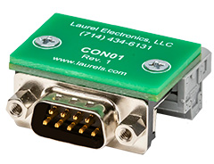
CON01 Connector
$75.00CBL6
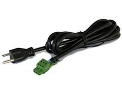
6-foot Power Cable
$41.00CBL12
12-foot Power Cable
$47.00CBL02
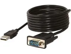
USB-to-RS232 Adapter Cable
$47.00CBL04
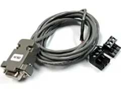
RS232 Cable for LT Transmitters
$47.00The Laureate™ LTE Series DIN rail transmitter for RTD temperature provides a linearized, highly accurate, stable and repeatable output for 100 ohm platinum, 10 ohm copper, and 120 ohm nickel RTDs. Pt100 platinum RTDs can have a DIN alpha of 0.003850 or ANSI alpha of 0.003902. The RTD type and temperature range, specified in °C or °F, are user-selectable, as narrow as 150 counts (such as 15.0°), limited only by electrical noise and digital filtering time constants.
Platinum Pt100 DIN (alpha 0.003850): -202°C to +850°C, ±0.03°C ±0.01% of reading, calibrated per IEC 751 (IPTS-68). Platinum Pt100 ANSI (alpha 0.003902): -202°C to +850°C, ±0.04°C ±0.01% of reading, calibrated per NIST Monograph 126. Nickel Ni120: -80°C to +260°C, ±0.05°C ±0.01% of reading. Copper Cu10: -100°C to +260°C, ±0.05°C ±0.01% of reading. Excitation current is 196 µA for Pt100 and Ni120, and 5.0 mA for Cu10.
In 4-wire hookup, different pairs of leads apply the excitation current and sense the voltage drop across the RTD, so the IR drop across the excitation leads is not a factor. In 3-wire hookup, the transmitter senses the combined voltage drop across the RTD plus two excitation leads, also senses the voltage drop across one excitation lead, and subtracts twice this voltage from the combined total — this technique effectively subtracts all lead resistance and compensates for ambient temperature changes if the two excitation leads are identical. In 2-wire hookup, the transmitter senses the combined voltage drop across the RTD and both lead wires; lead wire voltage drop can be measured by shorting out the RTD during setup and automatically subtracted, but changing lead wire resistance due to ambient temperature will not be compensated. Sensor lead resistance tempco is 10 mdeg/Ω/deg for 2-wire (up to 10Ω), and 10 µdeg/Ω/deg for 3- and 4-wire (up to 100Ω).
Zero tempco is ±0.03 deg/deg. Span tempco is ±0.003% of reading/°C. Overvoltage protection is 125 Vac. Open sensor indication is standard, selectable as 0 mA or greater than 20 mA output. Instrument Setup Software provides for user calibration (multiplier of RTD resistance plus offset in degrees) for RTDs whose resistance differs from nominal at 0°C. The same signal conditioner board can be user configured for all RTD types listed, in °C or °F, as well as for resistance measurement.
Standard Ethernet Data I/O is 10/100 Base-T per IEEE 802.3, isolated to 250V rms working / 2.3 kV rms per 1 minute test, with Modbus TCP at digital address 247. Analog output levels are 4-20 mA and 0-10 Vdc (selectable), 16-bit resolution, ±0.02% of output span accuracy, and 50 ms step response time.
Documented specification lists these as genuinely separate accuracy figures tied to two different calibration standards — IEC 751 (IPTS-68) for the DIN alpha curve versus NIST Monograph 126 for the ANSI alpha curve — since these are documented as distinct calibration references with their own characterization data, the resulting achievable accuracy figures for each curve are documented separately rather than being identical simply because both use 100Ω platinum elements.
Documented figures specifically quantify this difference in lead-resistance-driven temperature error per ohm per degree — since 3- and 4-wire configurations are documented as actively compensating for or eliminating lead resistance effects (through excitation/sense lead separation), while 2-wire configuration is documented as only compensating for the initial resistance value measured at setup (not its later temperature-driven drift), the residual documented tempco for 2-wire is substantially larger, reflecting the lead wire's own resistance change with ambient temperature going uncompensated.
No — documented description specifically qualifies the 3-wire compensation technique as effective "if the two excitation leads are identical," meaning the method's accuracy depends on this stated assumption; if the two excitation leads genuinely differ in resistance (due to length, gauge, splices, or connection quality), the documented subtraction of "twice one excitation lead's voltage drop" would not perfectly cancel the actual combined lead resistance, since the calculation assumes both leads' resistance is the same as the one it's actually measuring.
Documented description specifically explains that 2-wire hookup senses the combined voltage drop across the RTD and both lead wires together, with no separate, independent way to isolate just the lead wire contribution during normal operation; shorting the RTD during setup is documented as the specific method used to capture just the lead wire resistance in isolation at that moment, which is then subtracted — but since this is a one-time setup measurement, documented limitation notes any later lead resistance change from ambient temperature won't be automatically compensated the way it is in 3- and 4-wire configurations.
The page documents user calibration specifically as addressing RTDs "whose resistance is different than nominal at 0°C," which is consistent with correcting a manufacturing tolerance or small resistance offset at the reference point — this is documented as a distinct concern from selecting the correct underlying RTD type/alpha curve at time of order (P385 for DIN alpha, P392 for ANSI alpha), so a genuinely mismatched alpha curve would need the correct P385/P392 signal input selected, rather than being correctable solely through the documented user calibration multiplier/offset.
Documented specification lists these substantially different excitation currents without detailing the underlying circuit reasoning — this is consistent with Cu10's documented much lower base resistance (9.035Ω at 0°C, versus 100Ω for Pt100 and 120Ω for Ni120) requiring proportionally more excitation current to develop a comparably measurable voltage signal across the sensor for the same signal conditioning circuitry to process accurately.
Yes — this page documents Modbus TCP specifically as the supported Ethernet Data I/O protocol at digital address 247, while the LT Series serial variant is documented elsewhere as separately supporting Modbus RTU/ASCII and Laurel Custom ASCII; a control system needing a protocol other than Modbus TCP would need to reference the LT Series serial variant rather than this LTE Ethernet variant.
Documented note specifically states the board "can be user configured for all RTD types listed... as well as for resistance measurement," which is consistent with resistance measurement being an available configuration option on the same underlying board hardware — though the page itself doesn't detail whether this reconfiguration is purely a software/setup change or also involves jumper settings, similar to how DC voltmeter versus ammeter operation is documented as jumper-selected on other LT/LTE transmitters.
No — these are documented as two separate specifications describing different aspects of temperature-driven measurement drift: zero tempco describes drift in the reading at the zero/reference point, while span tempco describes drift in the overall scaling of readings across the measurement range as ambient temperature changes; both contribute to total measurement drift but through documented, physically distinct mechanisms.
No — documented accuracy is expressed as a fixed error figure (such as ±0.03°C for Pt100 DIN) plus a separate ±0.01% of reading component; the percentage-of-reading portion is documented as applying proportionally regardless of the specific span selected, while the fixed error figure remains constant, meaning total accuracy at any given actual temperature reading follows the same documented formula whether a wide or narrow input span is configured.
Documented explanation specifically notes a 100-ohm platinum RTD changes resistance by only about 0.385 ohms per degree Celsius — since this per-degree resistance change is so small, documented calculation shows a lead resistance of just 2 ohms can translate into roughly a 5°C measurement error, illustrating how the RTD's inherently small resistance-per-degree sensitivity makes it disproportionately vulnerable to any uncompensated lead resistance.
Documented field examples specifically cite a splice or repair performed on one conductor but not the other, a field repair using mismatched wire gauge because it was what was available on hand, and a corroded or loose terminal adding resistance on just one side of the pair — these are documented as genuine, common real-world causes of the two "identical" excitation leads becoming measurably mismatched over an installation's service life.
Yes — documented field test specifically involves swapping any two of the three lead wires at the controller terminals; if the temperature reading changes significantly after the swap, documented guidance identifies this as indicating a wiring fault, since a properly wired and matched 3-wire RTD installation is documented as showing the same reading regardless of which two wires are swapped.
Documented explanation specifically attributes this to the 4-wire configuration's completely separate voltage-sensing wire pair carrying essentially zero current, due to the high-impedance nature of a voltage measurement input — since negligible current flows through those sensing wires, their resistance has essentially zero effect on the reading regardless of length or mismatch, which documented analysis contrasts directly with 3-wire's dependence on the "leads are identical" assumption.
It genuinely introduces new error, documented as worse than simply reverting to 2-wire performance — one documented worked example specifically shows a normal, well-matched 3-wire installation producing 0.00°F of lead-related error, while jumpering the two excitation leads at the transmitter produces a documented +0.94°F error purely from that jumper, illustrating the jumper doesn't just remove the 3-wire compensation benefit but actively creates a new, uncompensated resistance path.
It's documented as a genuine, practical best practice with a measurable accuracy benefit — documented guidance specifically states using the same type of wire on all three RTD lead wires makes a 3-wire installation "as accurate as possible," directly tying the practical wire-selection decision to the underlying mathematical assumption (identical lead resistance) that the entire 3-wire compensation technique depends on.
Yes — one documented comparison specifically cites 3-wire RTDs as typically achieving ±0.5 to 1°C accuracy compared to ±1 to 5°C for 2-wire configurations, assuming lead wires up to 100 feet in length; this documented range gives a concrete sense of the real accuracy gap between the two configurations under a common practical installation length.
No — documented guidance specifically warns against grounding both ends of a shielded RTD cable, since doing so creates a ground loop that introduces noise rather than rejecting it; documented best practice specifically recommends grounding the shield only at the controller or cabinet side, leaving the sensor end of the shield unconnected.