
Features
- Two independently scalable totals for Channels A & B
- Inputs from NPN or PNP proximity switches, contact closures, digital logic, or magnetic pickups down to 12 mV, pulse rates to 1 MHz
- Two independently field-scalable pulse input channels
- Up counting from zero to preset value using positive scale factor
- Down counting from preset to zero using negative scale factor
- Totals stored in non-volatile memory
- 4-20 mA, 0-20 mA, 0-10V or -10V to +10V transmitter output, (isolated)
- Analog output resolution 0.0015% of span, accuracy ±0.02% of span
- Ethernet data I/O, Modbus TCP
- Dual 120 mA solid state relays for alarm or control (isolated)
- 5V, 10V, 12V, or 24V dc transducer excitation output (isolated)
- Power 85-264 Vac / 90-300 Vdc or 10-48 Vdc / 12-32 Vac (isolated)
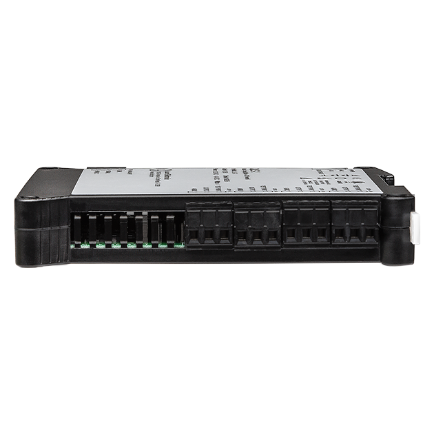
- DIN rail mount housing, 22.5 mm wide, detachable screw-clamp connectors
- Operating temperature from -40°C to 70°C (-40°F to 158°F)
Optional - Extended allows plus rate and total simultaneously, ratio (A/B), draw (A/B-1), other arithmetic functions (AxB, A+B, A-B), phase angle, stopwatch, up/down counting, batching operation, linearization of nonlinear inputs.
Certificates of Compliance
The Laureate 4-20 mA, 0-20 mA, 0-10V or -10V to +10V and ethernet output transmitter for pulse input to 4-20 mA converter and serial data output accepts two independently scalable input channels from a wide range of pulse sources, such as NPN or PNP proximity switches, contact closures, digital logic, magnetic pickups down to 12 mV, or AC voltages to 250 Vac. Input pulse rates can be as high as 1 MHz.
With a Standard main board, the transmitter output can be scaled to track total (such as gallons) or rate (such as gallons per minute). Square root extraction is standard.
With an Extended main board, the transmitter can also:
- Count up to a preset or down from a preset to zero. Such applications typically utilize the transmitter's two solid state relays, which are standard. External reset of totals is via a special three-position screw terminal connector.
- Perform custom-curve linearization on rate or total, for example to extend the range of transducers. Exceptionally accurate custom-curve linearization is provided by a curvilinear spline fit with up to 180 data points.
- Combine channels A and B arithmetically so that the transmitter output tracks A+B (e.g., sum of two flows or totals), A-B (e.g., difference of two flows or totals), AxB (e.g., horsepower as product of force and RPM), A/B (ratio of two flow or totals), and A/B-1 (draw or relative elongation of material between rollers).
The dual-channel signal conditioner used for pulse detection accepts inputs from proximity switches with PNP or NPN output, TTL or CMOS logic, magnetic pickups, contact closures, and other signals from 12 mV to 250 Vac. Jumper selections provide optimum operation for different sensor types and noise conditions. A built-in 5V, 10V or 24V dc excitation supply can power proximity switches and other sensors, and eliminate the need for an external power supply.
Exceptional Accuracy and Stability. Laureate transmitters determine frequency by taking the inverse of period as measured with a calibrated quartz crystal time base. This results in extremely accurate and stable 6-digit internal readings (±999,999 counts), which are then processed in software. The analog output is generated by an ultra-linear 16-bit (65,536 step) digital-to-analog converter (DAC) for 0.02% output accuracy. The update rate of the transmitter output is a programmed gate time + 30 ms + 0-2 signal periods. For a 60 Hz signal, the update rate would be 20 per second. Such fast update rates are ideal for alarm and control.
The update rate of the transmitter output is a programmed gate time + 30 ms + 0-2 signal periods. For a 60 Hz signal, the update rate would be 20 per second. Such fast update rates are ideal for alarm and control.
All signal conditioner board ranges are factory-calibrated, with calibration factors for each range securely stored in an onboard EEPROM. These factors can be scaled via software to accommodate external shunts, enabling field replacement of signal conditioner boards without necessitating recalibration of the associated transmitter. For optimal accuracy, factory recalibration is recommended annually. All Laurel Electronics instruments undergo factory calibration using the industry-leading Fluke calibrators, which are recalibrated yearly and certified traceable to national standards, ensuring the highest level of precision and reliability.
Laureate Transmitters are easily programmed with Laurel’s free Instrument Setup Software, downloadable from our website and compatible with Windows PCs, requiring a data interface board for setup.
Standard Features of Laureate LTE Transmitters Include:
- Ethernet I/O, (isolated). The supported protocols are Modbus RTU and ASCII, which are tunneled via Modbus TCP. Note that RS232 or RS485 data I/O is provided by Laurel's LT Series transmitters.
- 4-20 mA, 0-20 mA or 0-10V analog transmitter output, (isolated), jumper-selectable and user scalable. All selections provide 16-bit (0.0015 ) resolution of output span and 0.02% output accuracy of a reading from -99,999 to +99,999 counts that is also transmitted digitally. Output isolation from signal and power grounds eliminates potential ground loop problems. The supply can drive 20 mA into a 500 ohm (or lower) load for 10V compliance, or 10V into a 5K ohm (or higher) load for 2 mA compliance.
- Dual-channel pulse inputs for voltage signals, NPN or PNP proximity switches, contact closures, magnetic pickups or flow meters.
- Dual solid state relays, (isolated). Available for local alarm or control. Rated 120 mA at 130 Vac or 180 Vdc.
- Selectable transducer excitation output, (isolated), user selectable 5V@100 mA, 10V@120 mA, 12V@100 mA or 24V@50 mA.
- Power 85-264 Vac, (isolated), low-voltage 10-48 Vdc or 12-32 Vac power is optional.
Digital signal filtering modes can be selected to ensure stable readings in electrically noisy environments.
- An unfiltered selection provides true peak and valley readings and aids in control applications.
- A batch average filter selection averages each 16 conversions.
- An adaptive moving average filter selection provides a choice of 8 time constants from 80 ms to 9.6 s. When a significant change in signal level occurs, the filter adapts by briefly switching to the shortest time to follow the change, then reverts back to its selected time constant. An Auto setting selects the time constant selection based on signal noise.
Peak and valley values are automatically captured. These may be displayed via Laurel's free Instrument Setup Software, which runs on a PC under MS Windows or can be transmitted as serial data.
Two control inputs (CMOS/TTL levels, logic 0 = tied to digital ground, logic 1 = open) or dry contacts that can be set to control / activate 14 transmitter commands.
An (isolated) 5, 10, 12, or 24 Vdc excitation output is standard to power transducers or two-wire transmitters. Ratiometric operation, which automatically compensates for changes in the applied excitation, is jumper selectable for applications, such as bridges, where the signal to be measured is proportional to the excitation level.

LTE series DIN rail transmitters & signal conditioners can be interfaced to a wide range of sensors and transducers using one of seven available plug-in signal conditioner boards. The transmitters duplicate the high performance (high accuracy, high read rate) and extensive programmable features of Laureate 1/8 DIN digital panel meters, counters and timers. They utilize the same signal conditioners boards, much of the same firmware, and Laurel's free Windows-based Instrument Setup Software. They come in a compact DIN rail mount package with detachable screw-clamp connectors for easy wiring.
The LTE series Transmitters accessible from this page include a 4-20 mA, 0-20 mA, 0-10V, or -10V to +10V analog output (isolated, user selectable), an ethernet serial data interface (isolated, user selectable), and dual 120 mA solid state AC/DC relays (isolated). An (isolated) 5, 10, 12, or 24 Vdc transducer excitation output is included with all models other than those with a temperature or AC RMS signal conditioner.
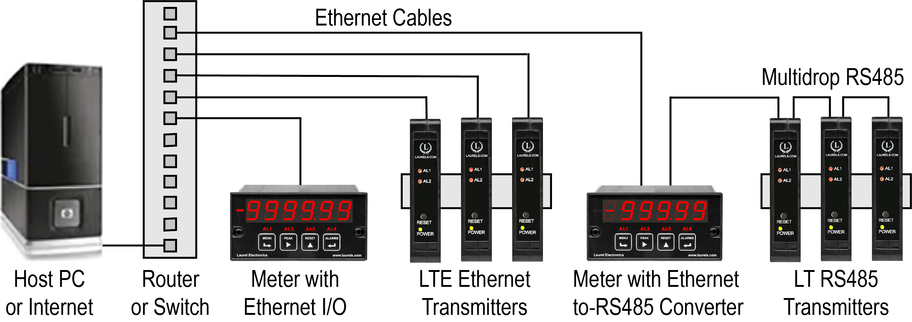
Connecting Laureate LTE Transmitters to a Local Area Network (LAN)
Laurel LTE series Ethernet transmitters can connect directly to a LAN via an Ethernet cable. Up to 30 Laureate LT Transmitters and/or Digital Panel Meters can be configured for RS485 and daisy-chained to an LT Transmitter for seamless LAN integration. Setup for both configurations is streamlined using Laurel’s free Instrument Setup Software, which simplifies node discovery and transmitter configuration.
Flexible Communication Options for LTE Transmitters
Laureate Transmitters can be equipped with Laurel communication boards to support various interfaces and protocols. These include serial interfaces with ASCII or Modbus RTU protocols, and Ethernet interfaces with web access, ASCII, or Modbus TCP/IP protocols, ensuring versatile connectivity for your commercial applications.
| LTE Transmitter Signal Input & Function | Model Series | Analog Output | Ethernet I/O | Dual Relays | |
|---|---|---|---|---|---|
| 1 | DC Input Voltage and Current | LTE-DC |  |
|
|
| 2 | AC RMS Voltage or Current | LTE-RMS | |
|
|
| 3 | Process Voltage or Current | LTE-P | |
|
|
| 4 | Strain Gauge or Potentiometer Follower | LTE-SG | |
|
|
| 5 | Weighing Applications | LTE-WA | |
|
|
| 6 | Load Cell & Microvolt Signals | LTE-WM | |
|
|
| 7 | Thermocouple (Types J, K, T, E, N, R, S) | LTE-TC | |
|
|
| 8 | RTD Temperature | LTE-RTD | |
|
|
| 9 | Resistance in Ohms | LTE-R | |
|
|
| 10 | Frequency, Rate, Speed | LTE-FR | |
|
|
| 11 | Pulse Input Totalizer | LTE-FR | |
|
|
| 12 | Process Signal Totalizer | LTE-VF | |
|
|
| 13 | Batch Controller Analog Input | LTE-FR | |
|
|
| 14 | Batch Controller Pulse Input | LTE-FR | |
|
|
| 15 | Sum, Difference, Ratio, Product of 2 Inputs | LTE-FR | |
|
|
| 16 | On/Off Duty Cycle | LTE-FR | |
|
|
| 17 | Stopwatch Timing for Single Events | LTE-FR | |
|
|
| 18 | Average Time of Periodic Events | LTE-FR | |
|
|
| 19 | AC Phase Angle and Power Factor | LTE-FR | |
|
|
| 20 | Quadrature Position or Rate | LTE-QD | |
|
|
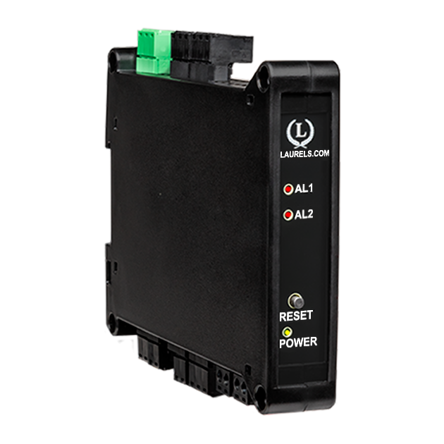
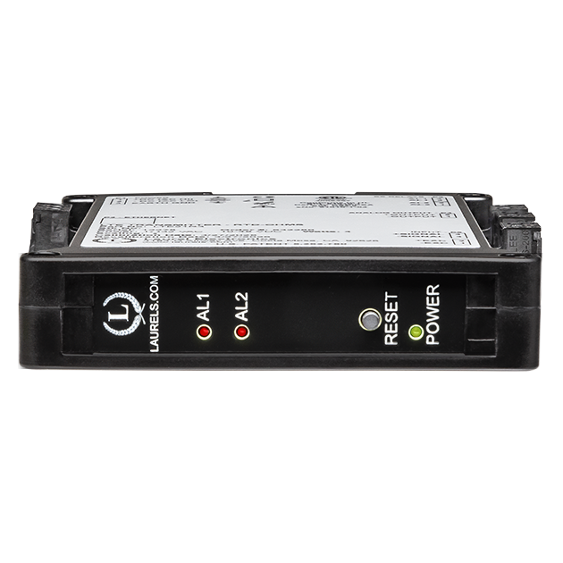
Laureate™ Ethernet & 4-20 mA Output Transmitter with Dual Pulse Totalizer Inputs
| Pulse Input | ||||
|---|---|---|---|---|
| Types | AC, pulses from NPN, PNP transistors, contact closures, magnetic pickups | |||
| Signal Ground | Common ground for channels A & B. | |||
| Minimum Signal | Nine ranges from (-12 to +12 mV) to (+1.25 to +2.1V). | |||
| Maximum Signal | 250 Vac | |||
| Maximum Frequency | 1 MHz, 30 kHz, 250 Hz (selectable). | |||
| Contact Debounce | 0, 3, 50 ms (selectable). | |||
| Recalibration: All ranges are calibrated at the factory. Recalibration is recommended every 12 months. | ||||
| Analog Output (standard) | ||||
| Output Levels | 4-20 mA and 0-10 Vdc (selectable) | |||
| Compliance, 4-20 mA | 10V (0-500Ω load) | |||
| Compliance, 0-10V | 2 mA (5 kΩ load) | |||
| Output Resolution | 16 bits (65,536 steps) | |||
| Output Accuracy | 0.02% of output span | |||
| Output Update Rate | Programmed gate time + 30 ms + 0-2 signal periods | |||
| Output Isolation | 250V rms working, 2.3 kV rms per 1 minute test | |||
| Ethernet Data I/O (standard) | ||||
| Type | 10/100 Base-T Ethernet per IEEE 802.3 | |||
| Data Rates | 300, 600, 1200, 2400, 4800, 9600, 19200 baud | |||
| Output Isolation | 250V rms working, 2.3 kV rms per 1 min test | |||
| Serial Protocol | Modbus TCP | |||
| Modbus Compliance | Modbus over Serial Line Specification V1.0 (2002) | |||
| Digital Addresses | 247 | |||
| Dual Relay Output (standard) | ||||
| Relay Type | Two solid state relays, SPST, normally open, Form A | |||
| Load Rating | 120 mA at 140 Vac or 180 Vdc | |||
| Excitation Output (standard) | ||||
| 5 Vdc | 5 Vdc ± 5%, 100 mA (jumper selectable) | |||
| 10 Vdc | 10 Vdc ± 5%, 120 mA (jumper selectable) | |||
| 12 Vdc | 12 Vdc ± 5%, 100 mA (jumper selectable) | |||
| 24 Vdc | 24 Vdc ± 5%, 50 mA (jumper selectable) | |||
| Output Isolation | 50 Vdc from signal ground | |||
| Power Input | ||||
| Standard Power | 85-264 Vac or 90-300 Vdc | |||
| Low Power Option | 10-48 Vdc or 12-32 Vac | |||
| Power Frequency | DC or 47-63 Hz | |||
| Power Isolation | 250V rms working, 2.3 kV rms per 1 min test | |||
| Power Consumption | 2.5W typical at 24V, 4.0W with max excitation output | |||
| Environmental | ||||
| Operating Temperature | -40°C to 70°C (-40°F to 158°F) | |||
| Storage Temperature | -40°C to 85°C (-40°F to 185°F) | |||
| Relative Humidity | 95% at 40°C, non-condensing | |||
| Cooling Required | Mount transmitters with ventilation holes at top and bottom. Leave 6 mm (1/4") between transmitters, or force air with a fan. | |||
| Mechanical | ||||
| Enclosure | Rugged black polycarbonate housing material | |||
| Mounting | 35 mm rail per DIN EN 50022 | |||
| Dimensions | 129 x 104 x 22.5 mm case | |||
| Connectors | Detachable screw clamp connectors meet VDE / IEC / UL / CSA standards. RJ45 jack for Ethernet | |||
| Tightening Torque | Screw terminal connectors: 5 lb-in (0.56 Nm) | |||
| Weight | Complete transmitter: 183 g (6.5 oz) | |||
| Replacement Case Screws | ||||
| Size | 6 | |||
| Thread Pitch | 6-19 | |||
| Length | 1/2" | |||
| Head Style | Pan Head | |||
| Drive Style | Phillips | |||
| Head Diameter | 0.256-0.270 | |||
| Head Height | 0.087-0.097 | |||
| Full/Partial Thread | Full | |||
| Drive Size | 2 | |||
| Material | Steel | |||
| Finished | Black Oxide | |||
| General | ||||
| Programming | Utilize Laurel's free Instrument Setup Software, which runs on a PC under MS Windows. | |||
| Security | Lockout options available using Laurel's free Instrument Setup Software. | |||
| Warranty | 3 years parts & labor | |||
| Recalibration: All ranges are calibrated at the factory. Recalibration is recommended every 12 months. | ||||
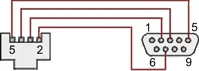
Transmitter Pinout
Free Instrument Setup Software for Series 2 Laureates
|
|
| 1/8 DIN Digital Panel Meters | DIN Rail Transmitters |
Free Downloadable Windows-based Instrument Setup (IS) software (Data Interface Board Required) for use with our programmable Digital Panel Meters, Scale Meters, Counters, Timers, Remote Displays, and Transmitters, are an easy method to set up Laureate 1/8 DIN digital panel meters, counters, timers, remote displays, and DIN-rail transmitters, as explained in the Instrument Setup Software Manual. Laureate 1/8 DIN instruments can also be set up from the front panel, as explained in their respective Owners Manuals. Instrument Setup software is of benefit whether or not the PC is connected to the instrument.
- When the PC is connected to the instrument, Instrument Setup software can retrieve the setup file from the instrument or open a default setup file or previously saved setup file from disk View Setup, then provides graphical user interface (GUI) screens with pull-down menus applicable to input, display, scaling, filtering, alarms, communications, analog output, and front panel lockouts. Fields that are not applicable to the instrument as configured are either left out or grayed out. Clicking on any item will bring up a detailed Help screen for that item. After editing, the setup file can be downloaded, uploaded to the instrument, or saved to a disk. The same setup file can then be downloaded into multiple instruments.
- When the PC is not connected to the instrument, the above GUI screens can be used to set up a virtual instrument. The setup file can then be saved to disk. Switching toView Menu then brings up a screen with the required front panel programming steps. This view can be printed out for use at the instrument site and to serve as a hard copy record.
Download Free Instrument Setup Software
Installation
Set User Account Control (UAC) of MS Windows to "Never notifiy me" so that Instrument Setup Software can create directories. The UAC change screen can be reached as follows:
- Under Windows 7, click on the Windows Start button in the lower left of the desktop and enter "UAC" in the search field.
- Under Windows 8, navigate to Control Panel, then to the "User Accounts and Family Safety" section, and click on "Change User Account Control Settings."
- Under Windows 10, click on the Windows Start button in the lower left of the desktop, then on "Settings", and enter "UAC" in the search field.
- Reboot your computer for the changed UAC setting to take effect.
RJ11-to-DB9 cable with rear view of DB9 connector to PC

RS232 cable, meter to PC, P/N CBL01
Laureate 1/8 DIN Laureate instruments must be equipped with a serial communications board and be connected to the computer via a serial communications cable. The connection can be via RS232, RS485, USB or Ethernet. Following setup, the serial communications board may be removed from the instrument if desired. The wiring of the RS232 cable is illustrated above with end views of the two connectors.
Laureate LT Series transmitters come standard with a 3-wire serial interface, which can be jumpered for RS232 or RS485.
Laureate LTE Series transmitters come standard with an Ethernet interface.
Meter Setup Screens
Click on any of the reduced screens below for a full-size screen view, then click on the Back button of your browser to return to this page. The screens examples below are for a fully-loaded Series 2 Digital Panel Meter (DPM), which is connected to the PC via RS232. If the meter is a Series 1 meter (pre-2007), this is sensed by the software, and somewhat different screens are brought up. Please see Series 1 setup screens.

Welcome Screen
From the computer desktop, click on Start > Programs > IS2 > IS2. Or click on the IS icon on your desktop. This splash screen will be displayed for three seconds. The software revision number is in the lower right.


Communications Selection Screen
Specify your desired communication protocol and the serial communications bus type, which should match the jumper setup of the instrument. Select None if the PC is not connected to the instrument.

Establish Communications Screen
If you selected RS-232, you will be asked to specify the PC Com Port and Baud Rate, which should match the jumper setup of the instrument. Click on Establish. With the right settings, the Communications Established field will light up in green, and the Meter Type will be recognized. If so, click onMain Menu.

Main Menu Screen
Click on File > Default Setup to retrieve the default setup file from disk for your type of meter. Click on File > Open Setupto retrieve a previously saved setup file from disk or on File > Save Setup to save your edited setup file to disk. Click onDPM > Get Setup to retrieve the setup file from your meter or on DPM > Put Setup to download your edited setup file into the meter.

DPM Input + Display Setup Screen
From the Main Menu, click on View > Setup, then on theInput+Display tab. You can now specify the meter hardware, signal type, display mode, and functions of control inputs A and B. Clicking on any item brings up a pull-down menu with the available choices.

DPM Scaling Setup Screen
Click on the Scaling tab, which provides three scaling methods to relate the signal to the displayed reading: 1) Scale and Offset method, 2) Coordinates of two points method, and 3) Reading Coordinates of Two Points method. The last method uses actual high and low signals, and the computer will prompt you.

DPM Filter Setup Screen
Click on the Filter tab, which allows you to specify the digital filter time constant (if any), the adaptive filter threshold, and whether Peak / Valley values are filtered or unfiltered. As for all setup screens, clicking on the F1 key while an item is highlighted brings up a Help screen for that item, as illustrated.

DPM Relay Alarms Setup Screen
Click on the Relay Alarms tab, which allows you to set up Alarms 1 and 2 for the optional dual relay output board. Clicking on any of the four numeric fields changes these to green and brings up a special field to enter the desired numeric value, which is tied to the displayed reading.

DPM Communications Setup Screen
Click on the Communications tab so set up serial communications. In particular, you can special the Serial Protocol and the meter address if multiple meters are to be addressed on the same serial data line.

DPM Analog Output Setup Screen
Click on the Analog Out tab so set up the optional analog output board. Three output ranges are selectable, the endpoints of which can be tied to user-specified High and Low readings.

DPM Lockouts Setup Screen
Click on the Lockouts tab to check off menu items which will no longer be accessible from the front panel of the meter. This will simplify meter operation and prevent unintended setup changes.
Meter Setup Utilities

DPM Front Panel Setup Screen
As an aid to programming the meter from the front panel when a serial connection is not available, you can return to the Main Menu and click on View > Menu. The required sequence of front panel screens will then be displayed. Click on any step in the sequence for the meaning of each digit, as illustrated for the FILtEr step. For a hardcopy, simply press on Print.

DPM Jumper Setup Screen
Specify your desired communication protocol and the serial communications bus type, which should match the jumper setup of the instrument. Select None if the PC is not connected to the instrument.

DPM Jumper Setup Screens
Click on any of the displayed plug-in boards, and you will be presented with the jumper positions and electrical connections for your selected board. This minimizes the need to refer to the printed manual.

DPM Commands Screen
This page allows you set up external input, serial communications, an analog output proportional to the display (optional), and lockouts for Laureate digital counters. The grayed out area at the top right of the screen applies to Laureate remote displays.


Graphical Output Screens (not available with Ethernet)
From the Main Menu, click on Readings if your PC is connected to the meter. A pull-down menu then offers three choices: List, Plot and Graph.
- List presents the latest readings in a 20-row by 10-column table. Press Pause at any time to freeze the display. This is one method to capture peak readings.
- Plot generates a plot of readings vs. time in seconds. It effectively turns the DPM-PC combination into a printing digital oscilloscope.
- Graph generates a histogram where the horizontal axis is the reading and the vertical axis is the number of occurrences of readings. The display continually resizes itself as the number of readings increases.

DPM Calibration Screens
Click on the Scaling tab, which provides three scalClick on the Scaling tab, which provides three scaling methods to relate the signal to the displayed reading: 1) Scale and Offset method, 2) Coordinates of two points method, and 3) Reading Coordinates of Two Points method. The last method uses actual high and low signals, and the computer will prompt you.

Frequency Meter Calibration Screen
Calibration of the quartz crystal of the Laureate frequency meter requires the input of a known frequency from a calibrator. Apply the frequency, then enter the frequency in Hertz. Calibration will be automatic, with storage of the calibration factor stored in non-volatile memory.
Dimensions
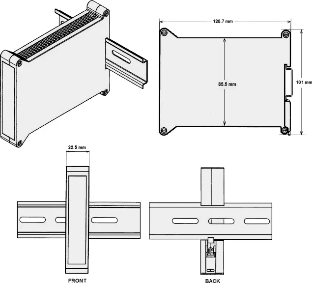
Dimensioned CAD assembly drawings in EPRT, STEP, x_t, .dwg, pdf file formats: Laureate-transmitter-case.zip (zipping prevents browser from opening CAD files as text files).
| Up/Down Totalizing | |
|---|---|
 |
Up/down totalizing is provided by a mode of the Extended totalizing transmitter where pulses are either added or subtracted on Channel A based on a direction input on Channel B. The unit can also be programmed so that counting by Channel A is inhibited by an input on Channel B. |
| Combining Two Totals | |
 |
A+B, A-B, A/B and AxB arithmetic functions are available with the Extended totalizing transmitter. A+B can sum two totals, while A-B subtracts the outflow total from inflow total. A/B ratio applied to two totals helps assure the proper mixing of components. |
| Up or Down Counting with Preset | |
 |
A single Laureate dual-channel totalizing transmitter will handle two repetitive fill operations by counting from zero up to a preset, or down from a preset to zero. The dual relay option is required. |
| Machine ON Time and Utilization | |
 |
An easy way to measure the ON time of machines is to count AC line cycles and scale the total to hours. To display machine utilization or duty cycle in percent, use the Extended totalizing transmitter. Connect Channel A to switched AC and Channel B to the AC line, and apply a 100 multiplier to the A/B ratio. |
| Custom Curve Linearization | |
 |
The Extended version of the Laureate dual channel totalizing transmitter can transmit scaled rate or total for the same channel at the push of a button, and alarm both the rate and total. The Extended version can also do curve linearization, thereby extending the working range and accuracy of flow transducers. |

CAL-Digital
Certificate of Calibration
$65.00


CBL02
USB-to-RS232 Adapter Cable
$47.00
CBL04
RS232 Cable for LT Transmitters
$47.00CBL12
12-foot Power Cable
$47.00CBL6
6-foot Power Cable
$41.00Understanding the Laureate™ LTE Series DIN Rail Transmitter for Pulse Input Totalizer
The Laureate™ LTE Series DIN rail transmitters for pulse input totalizer accepts two independently scalable input channels from a wide range of pulse sources, such as NPN or PNP proximity switches, contact closures, digital logic, magnetic pickups down to 12 mV, or AC voltages to 250 Vac. Input pulse rates can be as high as 1 MHz. With a Standard main board, the transmitter output can be scaled to track total (such as gallons) or rate (such as gallons per minute); square root extraction is standard.
Extended Main Board Capabilities
With an Extended main board, the transmitter can count up to a preset or down from a preset to zero (typically using the two standard solid state relays, with external reset via a special three-position screw terminal connector); perform custom-curve linearization on rate or total via a curvilinear spline fit with up to 180 data points; and combine Channels A and B arithmetically so the output tracks A+B, A-B, AxB, A/B, or A/B-1.
Real-World Applications
- Up/Down Totalizing — pulses are added or subtracted on Channel A based on a direction input on Channel B; counting can also be inhibited by a Channel B input.
- Combining Two Totals — A+B sums two totals; A-B subtracts outflow total from inflow total; A/B ratio applied to two totals helps assure proper mixing of components.
- Up or Down Counting with Preset — a single transmitter handles two repetitive fill operations, counting from zero up to a preset or down from a preset to zero; the dual relay option is required.
- Machine ON Time and Utilization — count AC line cycles and scale to hours for ON time; connect Channel A to switched AC and Channel B to the AC line, applying a 100 multiplier to the A/B ratio for duty cycle percent.
- Custom Curve Linearization — the Extended version transmits scaled rate or total for the same channel at the push of a button, alarms both, and extends the working range and accuracy of flow transducers.
Accuracy & Ethernet I/O
Totals are stored in non-volatile memory. Laureate transmitters determine frequency by taking the inverse of period as measured with a calibrated quartz crystal time base, producing stable 6-digit internal readings (±999,999 counts). Standard Ethernet Data I/O is 10/100 Base-T per IEEE 802.3, isolated to 250V rms working / 2.3 kV rms per 1 minute test, with Modbus TCP at digital address 247.
Where LTE Pulse Input Totalizer Transmitters Are Used
- Networked Flow Totalization — non-volatile total storage with Ethernet-connected readout.
- Multi-Component Batch Mixing — combined-total ratio verification for accurate composition.
- Dual-Station Fill Lines — two independent preset-based fill operations on one transmitter.
- Machine Runtime & Duty Cycle Monitoring — AC-line-cycle-based utilization tracking.
- Multi-Point Networked Totalizing — several transmitters on one Modbus TCP network.
- OEM Networked Totalizer Instrumentation — DIN rail integration into Ethernet-based control panels.
LTE Pulse Input Totalizer Transmitter Frequently Asked Questions
Does the documented storage of totals in non-volatile memory mean the transmitter continuously writes to that memory during every pulse count?
The page documents totals as being stored in non-volatile memory without detailing the specific write frequency or timing of that storage — this is consistent with periodic or event-driven writes rather than a write occurring on literally every single incoming pulse, since continuous per-pulse writes to non-volatile memory would be unusual practice given typical memory write-cycle endurance considerations, though the page itself doesn't specify the exact write interval.
Why does the documented "Machine ON Time and Utilization" application specifically apply a 100 multiplier to the A/B ratio to get duty cycle percent?
Documented description specifically frames duty cycle as the ratio of switched-AC cycles (Channel A) to total AC-line cycles (Channel B) — since a ratio expressed as a decimal fraction (such as 0.75 for 75% duty cycle) needs to be converted to a percentage for conventional duty-cycle reporting, the documented 100 multiplier is the standard mathematical step converting that raw A/B decimal ratio into the percentage figure operators expect to see displayed.
Does the documented "Up or Down Counting with Preset" application require the Extended main board, or is it available with the Standard board?
Documented description specifically lists this capability under the Extended main board's feature set, distinct from the Standard board's more basic total/rate tracking — the documented requirement for "the dual relay option" alongside this application further indicates it's built on Extended-board-level functionality, consistent with preset-based counting logic requiring the additional processing capability the Extended board provides over the Standard board.
Can the external reset for up/down counting with preset use any available control input, or is the documented three-position screw terminal specifically required?
Documented description specifically states external reset of totals is "via a special three-position screw terminal connector," identifying this as a specific, dedicated hardware connection point; this is consistent with the reset function being tied to that particular physical terminal arrangement rather than being freely assignable to any other general-purpose control input the transmitter may offer.
Does inhibiting Channel A counting via a Channel B input (in the documented up/down totalizing mode) pause the totalizer, or does it also affect the documented rate output?
The page documents this inhibit function specifically in the context of totalizing (accumulated count), without detailing whether a simultaneously active rate output would also be affected — since rate and total are documented elsewhere as distinct, separately trackable outputs (with the Extended board specifically able to display both), an inhibit applied to Channel A's counting is consistent with primarily affecting the accumulating total, though the specific interaction with a concurrently active rate calculation isn't detailed on this page.
Does this LTE Pulse Input Totalizer transmitter's documented Modbus TCP-only protocol limit compatibility compared to the RS232/RS485 LT Series totalizer variant?
Yes — this page documents Modbus TCP specifically as the supported Ethernet Data I/O protocol at digital address 247, while the LT Series serial variant is documented elsewhere as separately supporting Modbus RTU/ASCII and Laurel Custom ASCII; a control system needing a protocol other than Modbus TCP would need to reference the LT Series serial variant rather than this LTE Ethernet variant.
Does the documented custom curve linearization apply only to the totalized value, or can it also correct the rate reading?
Documented description specifically states the Extended version "can transmit scaled rate or total for the same channel at the push of a button, and alarm both the rate and total," and separately notes linearization "extends the working range and accuracy of flow transducers" — since both rate and total are documented as derived from the same underlying linearized signal processing for a given channel, custom curve linearization is documented as improving both the total and the rate reading together, not just one or the other.
Does the documented A/B ratio for combining two totals require both channels to have identical pulse-per-unit scaling factors?
The page documents A/B ratio applied to two totals as helping "assure the proper mixing of components," without stating that both channels must share identical scaling factors — since each channel is documented as independently scalable, the meaningful A/B ratio for a mixing application depends on both channels being correctly and consistently scaled to their own respective physical units (such as gallons for each), rather than requiring the raw, unscaled pulse counts from each channel to use identical scaling.
Does selecting the maximum documented pulse frequency (1 MHz) on Channel A affect the transmitter's documented totalizing accuracy?
The page documents 1 MHz as the maximum input pulse rate without listing a separate, reduced accuracy figure specifically tied to operating at that maximum frequency — the transmitter's documented crystal-timed period measurement approach is consistent with maintaining its stated accuracy across the specified frequency range, though extremely high pulse rates in any counting system can in principle be more sensitive to noise, which is why the page separately documents selectable noise filtering and contact debounce settings.
Does power consumption increase when the transducer excitation output is set to its maximum documented level, and by how much?
Yes — documented specification lists power consumption as "2.5W typical at 24V, 4.0W with max excitation output," directly quantifying the additional power draw when the transducer excitation output is set to its maximum documented level, representing a genuine, specified increase tied to how much excitation current is being supplied to an external sensor.
Totalizer Power-Fail Recovery & Non-Volatile Memory Questions From the Field
What specifically happens to an accumulated flow total during a power failure if a totalizer does NOT use non-volatile memory or a "save" mechanism?
Documented field guidance specifically warns that in some systems, the accumulated value resets on a power cycle unless total values are explicitly persisted to non-volatile memory — for critical applications, documented practice specifically recommends using a save/persist mechanism to write accumulated tags to non-volatile storage precisely to prevent this reset-on-power-loss behavior.
Does a totalizer's non-volatile EEPROM memory typically require an external battery to retain stored totals?
No — documented product descriptions specifically state that parameters and totals are stored in non-volatile EEPROM memory "which doesn't need any external battery," with documented power-fail features automatically saving the total flow reading and resuming from the same value after power is restored, without relying on a battery to bridge the power-off period.
Is there a documented technical reason non-volatile memory devices can encounter difficulty if power is interrupted specifically during a write operation, as opposed to during a read?
Yes — documented technical analysis specifically explains that non-volatile memory data is generally safe during read operations regardless of a power failure, but if power is interrupted during an active write process, some memory cells may end up with unstable, partially-written values; documented analysis further notes that simply checking already-stored values afterward may not reliably indicate where writing should resume, making mid-write power loss a genuinely different and more difficult failure mode than a read-time interruption.
Is there a documented recovery technique for locating a safe restart point in non-volatile memory after a power-loss event during writing?
Yes — one documented patent-level approach specifically describes scanning pages of a memory array to find the first free page after a power loss, marking that page as available, and directing the next write cycle to that specific located page; this documented method is specifically designed to safely resume operation without relying on potentially corrupted data from the interrupted write.
Does frequent non-volatile memory writing for totalizer updates create a documented long-term wear concern, separate from the power-failure issue itself?
Yes — documented technical analysis specifically identifies limited write endurance as an inherent characteristic of non-volatile memory technology, noting that frequent modifications to accumulating data can result in a significant number of writes over a device's service life; documented engineering approaches specifically address this by deferring or batching updates to minimize total non-volatile memory write overhead while still preserving data consistency.
Is there a documented practical example of a networked totalizer device specifically designed to prevent a totalization count from resetting after a power interruption?
Yes — one documented field discussion specifically describes a dedicated pulse-processing device that accumulates and stores the total pulse count (alongside instantaneous flow rate) in Modbus registers, with the pulse count specifically stored in non-volatile memory so the totalization count doesn't return to zero after a power loss, illustrating a genuine, deployed example of this design principle in networked flow totalizing equipment.
Does periodically accumulating flow rate into a running total (rather than counting raw pulses) introduce a documented accuracy tradeoff related to how frequently the accumulation occurs?
Yes — documented field discussion specifically describes this tradeoff using a worked example: accumulating flow rate into a total only once per hour is characterized as "not very good," with the documented recommendation to instead accumulate much more frequently (such as once per second, dividing the hourly rate figure accordingly) to achieve a genuinely accurate running total, illustrating that accumulation frequency itself is a real, quantifiable factor in totalizing accuracy for rate-based (versus raw pulse-count-based) totalizing methods.
Are non-volatile flow totalizers documented as suitable for use in flameproof or explosion-proof industrial enclosures?
Yes — one documented commercial flow totalizer example specifically describes a flameproof-execution model with non-volatile memory, an IP65-rated explosion-proof enclosure, and dual LED digital displays for flow rate and totalized flow, confirming that non-volatile-memory-based totalizing capability is documented as available and deployed even in hazardous-area-rated industrial instrument enclosures.
