New Front Panel USB-C Port Coming Soon!
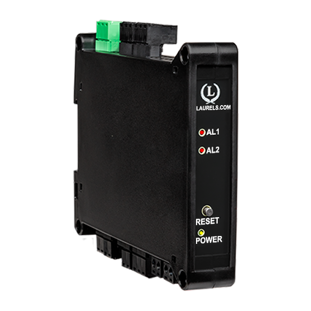
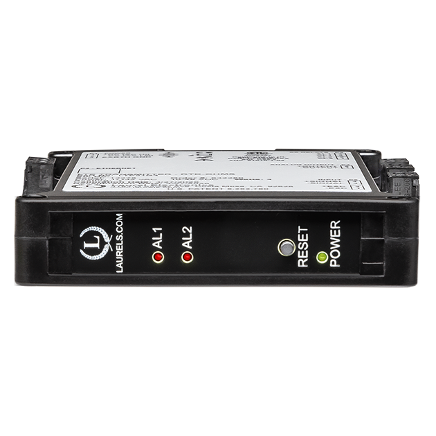
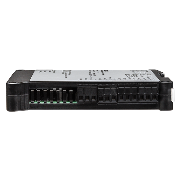
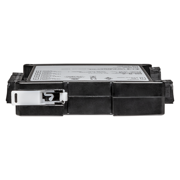
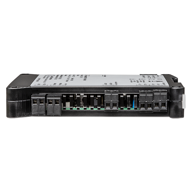
The Laureate 4-20 mA, 0-20 mA, 0-10V or -10V to +10V and RS232/RS485 output transmitter for batch controller is a low cost, powerful and highly accurate batching controller for repetitive fill operations. It can use the Laureate V-to-F analog signal conditioner for use with 4-20 mA, 0-1 mA or 0-10V conditioned flow meter signals. Relay control can be provided by two or four 8A contact relays, or by two or four 120 mA AC/DC solid state relays. Fill operations are repeated continually with a programmable delay from 10 ms to 199.99 sec, or based on an external control input.
Three items are tracked by the batch control software. These can each be scaled to engineering units of total or flow rate and displayed by the controller's six-digit LED display: Item #1 is the current batch total, which can be set up to count up from zero to a preset limit, or down from a preset limit to zero. Item #2 can be assigned to grand total or number of batches. Item #3 is the flow rate.
The analog input batch controller utilizes the Laureate VF voltage-to-frequency converter signal conditioner board, which converts 4-20 mA, 0-1 mA or 0-1V conditioned flow meter signals to a frequency from 10 kHz to 110 kHz. This allows the counter controller to totalize flow, to count up to a preset value, or to count down to zero from a preset value for batch control. One of the relays is dedicated to On/Off batch control, while the other relay is available to slow down rate near the setpoint or to provide another alarm or control function based on rate or total.
The Extended Laureate computer board can display rate based on successive readings. It also allows exceptionally accurate custom curve linearization, for example to read out liquid volume or rate of flow in a horizontal cylindrical tank based on level reported by a 4-20 mA transmitter. For setup, up to 180 data points can be input into a computer spreadsheet or text file by the user. The computer then calculates spline-fit segments, which are downloaded into the transmitter.
Exceptional Accuracy and Stability. Laureate transmitters determine frequency by taking the inverse of period as measured with a calibrated quartz crystal time base. This results in extremely accurate and stable 6-digit internal readings (±999,999 counts), which are then processed in software. The analog output is generated by an ultra-linear 16-bit (65,536 step) digital-to-analog converter (DAC) for 0.02% output accuracy. The update rate of the transmitter output is a programmed gate time + 30 ms + 0-2 signal periods. For a 60 Hz signal, the update rate would be 20 per second. Such fast update rates are ideal for alarm and control.
The update rate of the transmitter output is a programmed gate time + 30 ms + 0-2 signal periods. For pulse rates of 60 Hz and above, the update rate would be 20 per second. Such fast update rates are ideal for alarm and control.
All signal conditioner board ranges are factory-calibrated, with calibration factors for each range securely stored in an onboard EEPROM. These factors can be scaled via software to accommodate external shunts, enabling field replacement of signal conditioner boards without necessitating recalibration of the associated transmitter. For optimal accuracy, factory recalibration is recommended annually. All Laurel Electronics instruments undergo factory calibration using the industry-leading Fluke calibrators, which are recalibrated yearly and certified traceable to national standards, ensuring the highest level of precision and reliability.
Easy USB-C Programming: Configure Laureate transmitters through the front-panel USB-C port with Laurel’s free Instrument Setup Software for Windows. Configurations can be saved to the transmitter, a PC, a file server, or a USB thumb drive. Laurel’s free Instrument Setup Software can also be used for light-duty data collection.
Peak and valley values are automatically captured. These may be displayed via Laurel's free Instrument Setup Software, which runs on a PC under MS Windows or can be transmitted as serial data.
Two control inputs (CMOS/TTL levels, logic 0 = tied to digital ground, logic 1 = open) or dry contacts that can be set to control / activate 14 transmitter commands.
An (isolated) 5, 10, 12, or 24 Vdc excitation output is standard to power transducers or two-wire transmitters. Ratiometric operation, which automatically compensates for changes in the applied excitation, is jumper selectable for applications, such as bridges, where the signal to be measured is proportional to the excitation level.

LT series DIN rail Transmitters & signal conditioners can be interfaced to a wide range of sensors and transducers using one of seven available plug-in signal conditioner boards. The transmitters duplicate the high performance (high accuracy, high read rate) and extensive programmable features of Laureate 1/8 DIN digital panel meters, counters and timers. They utilize the same signal conditioners boards, much of the same firmware, and Laurel's free Windows-based Instrument Setup Software. They come in a compact DIN rail mount package with detachable screw-clamp connectors for easy wiring.
The LT series Transmitters accessible from this page include a 4-20 mA, 0-20 mA, 0-10V, or -10V to +10V analog output (isolated, user selectable), an RS232 or RS485 serial data interface (isolated, user selectable), and dual 120 mA solid state AC/DC relays (isolated). An (isolated) 5, 10, 12, or 24 Vdc transducer excitation output is included with all models other than those with a temperature or AC RMS signal conditioner.
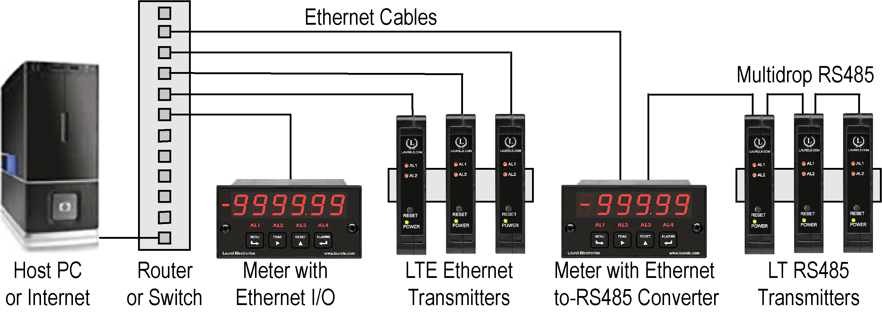
Up to 30 Laureate LT Transmitters and/or Digital Panel Meters can be configured for RS485 and daisy-chained to an LT Transmitter for seamless LAN integration. Alternatively, Laurel LTE series Ethernet transmitters can connect directly to a LAN via an Ethernet cable. Setup for both configurations is streamlined using Laurel’s free Instrument Setup Software, which simplifies node discovery and transmitter configuration.
Laureate Transmitters can be equipped with Laurel communication boards to support various interfaces and protocols. These include serial interfaces with ASCII or Modbus RTU protocols, and Ethernet interfaces with web access, ASCII, or Modbus TCP/IP protocols, ensuring versatile connectivity for your commercial applications.
| LT Transmitter Signal Input & Function | Model Series | Analog Output | RS232 & RS485 | Dual Relays | |
|---|---|---|---|---|---|
| 1 | DC Input Voltage and Current | LT-DC |  |
|
|
| 2 | AC RMS Voltage or Current | LT-RMS | |
|
|
| 3 | Process Voltage or Current | LT-P | |
|
|
| 4 | Weighing Applications | LT-WA | |
|
|
| 5 | Load Cell & Microvolt Signals | LT-WM | |
|
|
| 6 | Thermocouple (Types J, K, T, E, N, R, S) | LT-TC | |
|
|
| 7 | RTD Temperature | LT-RTD | |
|
|
| 8 | Resistance in Ohms | LT-R | |
|
|
| 9 | Frequency, Rate, Speed | LT-FR | |
|
|
| 10 | Pulse Input Totalizer | LT-FR | |
|
|
| 11 | Process Signal Totalizer | LT-VF | |
|
|
| 12 | Sum, Difference, Ratio, Product of 2 Inputs | LT-FR | |
|
|
| 13 | Batch Controller Pulse Input | LT-FR | |
|
|
| 14 | Batch Controller Analog Input | LT-FR | |
|
|
| 15 | On/Off Duty Cycle | LT-FR | |
|
|
| 16 | Stopwatch Timing for Single Events | LT-FR | |
|
|
| 17 | Average Time of Periodic Events | LT-FR | |
|
|
| 18 | AC Phase Angle and Power Factor | LT-FR | |
|
|
| 19 | Quadrature Position or Rate | LT-QD | |
|
|
| Pulse Inputs (FR signal conditioner) | ||||
|---|---|---|---|---|
| Signal Types | AC, pulses from NPN, PNP transistors, contact closures,magnetic pickups. | |||
| Ch A Frequency, Max | 1 MHz | |||
| Ch B Frequency, Max | 250 kHz | |||
| Signal Ground | Common ground for channels A & B | |||
| Minimum Signal | Nine ranges from (-12 to +12 mV) to (+1.25 to +2.1V) | |||
| Maximum Signal | 250 Vac | |||
| Maximum Frequency | 1 MHz, 30 kHz, 250 Hz (selectable) | |||
| Conversion Technique | Inverse period | |||
| Delay between batches | Selectable 10 ms to 199.99 s | |||
| Recalibration: All ranges are calibrated at the factory. Recalibration is recommended every 12 months. | ||||
| Power Supply Boards (one required) | ||||
| Voltage, standard | 85-264 Vac or 90-300 Vdc | |||
| Voltage, optional | 12-32 Vac or 10-48 Vdc | |||
| Frequency | DC or 47-63 Hz | |||
| Power consumption | 1.2W @ 120 Vac, 1.5W @ 240 Vac, 1.3W @ 10 Vdc, 1.4W @ 20 Vdc, | |||
| (typical, base meter) | 1.55W @ 30 Vdc, 1.8W @ 40 Vdc, 2.15W @ 48 Vdc | |||
| Power Isolation | 250V rms working, 2.3 kV rms per 1 min test | |||
| Excitation Output (standard) | ||||
| 5 Vdc | 5 Vdc ± 5%, 100 mA (jumper selectable) | |||
| 10 Vdc | 10 Vdc ± 5%, 120 mA (jumper selectable) | |||
| 12 Vdc | 12 Vdc ± 5%, 100 mA (jumper selectable) | |||
| 24 Vdc | 24 Vdc ± 5%, 50 mA (jumper selectable) | |||
| Output Isolation | 50 Vdc from signal ground | |||
| Analog Output Boards (one optional) | ||||
| Output Levels | 4-20 mA, 0-20 mA, 0-10V, -10 to +10V (single-output option) | |||
| Current compliance | 4-20 mA, 0-20 mA, 0-10V (dual-output option) | |||
| Voltage compliance | 2 mA at 10V ( > 5 kΩ load) | |||
| Scaling | 12V at 20 mA ( < 600 Ω load) | |||
| Resolution | Zero and full scale adjustable from -99999 to +99999 16 bits (0.0015% of full scale) | |||
| Isolation | 250V rms working, 2.3 kV rms per 1 min test (dual analog outputs share the same ground) | |||
| Relay Output Boards (one required for batch control) | ||||
| Dual magnetic relays | 2 Form C, 8A max, 440Vac or 125Vdc max, 2500VA or 300W | |||
| Quad magnetic relays | 4 Form A (NO), 8A max, 440Vac or 125Vdc max, 2500VA or 300W | |||
| Dual solid state relays | 2 Form A (NO), AC or DC, 0V - 400V, 120Ma, 35Ohms (max at On-State) | |||
| Quad solid state relays | 4 Form A (NO), AC or DC, 0V - 400V, 120Ma, 35Ohms (max at On-State) | |||
| Relay commons | Isolated commons for dual relays or each pair of quad relays | |||
| Relay isolation | 250V rms working, 2.3 kV rms per 1 minute test | |||
| Relay latching modes | Latching or non-latching | |||
| Relay active modes | Active on or off, active high or low | |||
| Hysteresis modes | QA passband mode, split hysteresis, span hysteresis | |||
| Communication Boards (one optional) | ||||
| Board Selections | RS232, RS485 with dual RJ11 connectors, RS485 with dual RJ45 connectors, USB, High-Speed Ethernet, USB-to-RS485 gateway, High-Speed Ethernet-to-RS485 gateway, WiFi with built-in antenna plus USB & RS485, WiFi with external antenna plus USB & RS485 | |||
| Protocols | Laurel Custom ASCII (serial), Modbus RTU (serial), Modbus TCP (Ethernet or WiFi) | |||
| Digital Addresses | 247 (Modbus), 31 (Laurel ASCII), | |||
| Isolation | 250V rms working, 2.3 kV rms per 1 min test | |||
| Environmental | ||||
| Operating Temperature | -40°C to 70°C (-40°F to 158°F) | |||
| Storage Temperature | -40°C to 85°C (-40°F to 185°F) | |||
| Relative Humidity | 95% at 40°C, non-condensing | |||
| Protection | NEMA-4X (IP-65) when panel mounted | |||
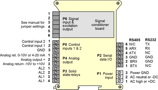
| Signal Connections | ||||
 |
||||
| Mechanical | ||||
| Enclosure | Rugged black polycarbonate housing material | |||
| Mounting | 35 mm rail per DIN EN 50022 | |||
| Dimensions | 129 x 104 x 22.5 mm case | |||
| Connectors | Detachable screw clamp connectors meet VDE / IEC / UL / CSA standards. RJ45 jack for Ethernet | |||
| Tightening Torque | Screw terminal connectors: 5 lb-in (0.56 Nm) | |||
| Weight | Complete transmitter: 183 g (6.5 oz) | |||
| Replacement Case Screws | ||||
| Size | 6 | |||
| Thread Pitch | 6-19 | |||
| Length | 1/2" | |||
| Head Style | Pan Head | |||
| Drive Style | Phillips | |||
| Head Diameter | 0.256-0.270 | |||
| Head Height | 0.087-0.097 | |||
| Full/Partial Thread | Full | |||
| Drive Size | 2 | |||
| Material | Steel | |||
| Finished | Black Oxide | |||
| General | ||||
| Programming | Utilize Laurel's free Instrument Setup Software, which runs on a PC under MS Windows. | |||
| Security | Lockout options include using the front panel buttons, the free Instrument Setup Software, or a hardware jumper. | |||
| Warranty | 3 years parts & labor | |||
| Recalibration: All ranges are calibrated at the factory. Recalibration is recommended every 12 months. | ||||
|
|
| 1/8 DIN Digital Panel Meters | DIN Rail Transmitters |
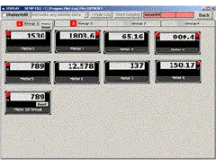
Free Downloadable Windows-based Instrument Setup (IS) software (Data Interface Board Required) for use with our programmable Digital Panel Meters, Scale Meters, Counters, Timers, Remote Displays, and Transmitters, are an easy method to set up Laureate 1/8 DIN digital panel meters, counters, timers, remote displays, and DIN-rail transmitters, as explained in the Instrument Setup Software Manual. Laureate 1/8 DIN instruments can also be set up from the front panel, as explained in their respective Owners Manuals. Instrument Setup software is of benefit whether or not the PC is connected to the instrument.
Set User Account Control (UAC) of MS Windows to "Never notifiy me" so that Instrument Setup Software can create directories. The UAC change screen can be reached as follows:
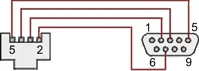
RJ11-to-DB9 cable with rear view of DB9 connector to PC
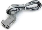
RS232 cable, meter to PC, P/N CBL01
Laureate 1/8 DIN Laureate instruments must be equipped with a serial communications board and be connected to the computer via a serial communications cable. The connection can be via RS232, RS485, USB or Ethernet. Following setup, the serial communications board may be removed from the instrument if desired. The wiring of the RS232 cable is illustrated above with end views of the two connectors.
Laureate LT Series transmitters come standard with a 3-wire serial interface, which can be jumpered for RS232 or RS485.
Laureate LTE Series transmitters come standard with an Ethernet interface.
Click on any of the reduced screens below for a full-size screen view, then click on the Back button of your browser to return to this page. The screens examples below are for a fully-loaded Series 2 Digital Panel Meter (DPM), which is connected to the PC via RS232. If the meter is a Series 1 meter (pre-2007), this is sensed by the software, and somewhat different screens are brought up. Please see Series 1 setup screens.


From the Main Menu, click on Readings if your PC is connected to the meter. A pull-down menu then offers three choices: List, Plot and Graph.


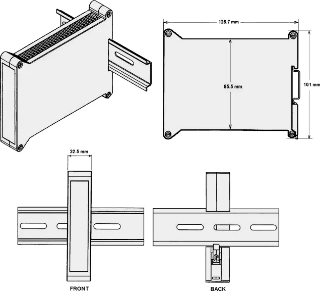
Dimensioned CAD assembly drawings in EPRT, STEP, x_t, .dwg, pdf file formats: Laureate-transmitter-case.zip (zipping prevents browser from opening CAD files as text files).
| Up/Down Totalizing | |
|---|---|
 |
Up/down totalizing is provided by a mode of the Extended totalizing transmitter where pulses are either added or subtracted on Channel A based on a direction input on Channel B. The unit can also be programmed so that counting by Channel A is inhibited by an input on Channel B. |
| Combining Two Totals | |
 |
A+B, A-B, A/B and AxB arithmetic functions are available with the Extended totalizing transmitter. A+B can sum two totals, while A-B subtracts the outflow total from inflow total. A/B ratio applied to two totals helps assure the proper mixing of components. |
| Up or Down Counting with Preset | |
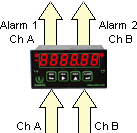 |
A single Laureate dual-channel totalizing transmitter will handle two repetitive fill operations by counting from zero up to a preset, or down from a preset to zero. The dual relay option is required. |
| Machine ON Time and Utilization | |
 |
An easy way to measure the ON time of machines is to count AC line cycles and scale the total to hours. To display machine utilization or duty cycle in percent, use the Extended totalizing transmitter. Connect Channel A to switched AC and Channel B to the AC line, and apply a 100 multiplier to the A/B ratio. |
| Custom Curve Linearization | |
 |
The Extended version of the Laureate dual channel totalizing transmitter can transmit scaled rate or total for the same channel at the push of a button, and alarm both the rate and total. The Extended version can also do curve linearization, thereby extending the working range and accuracy of flow transducers. |
CAL-Digital
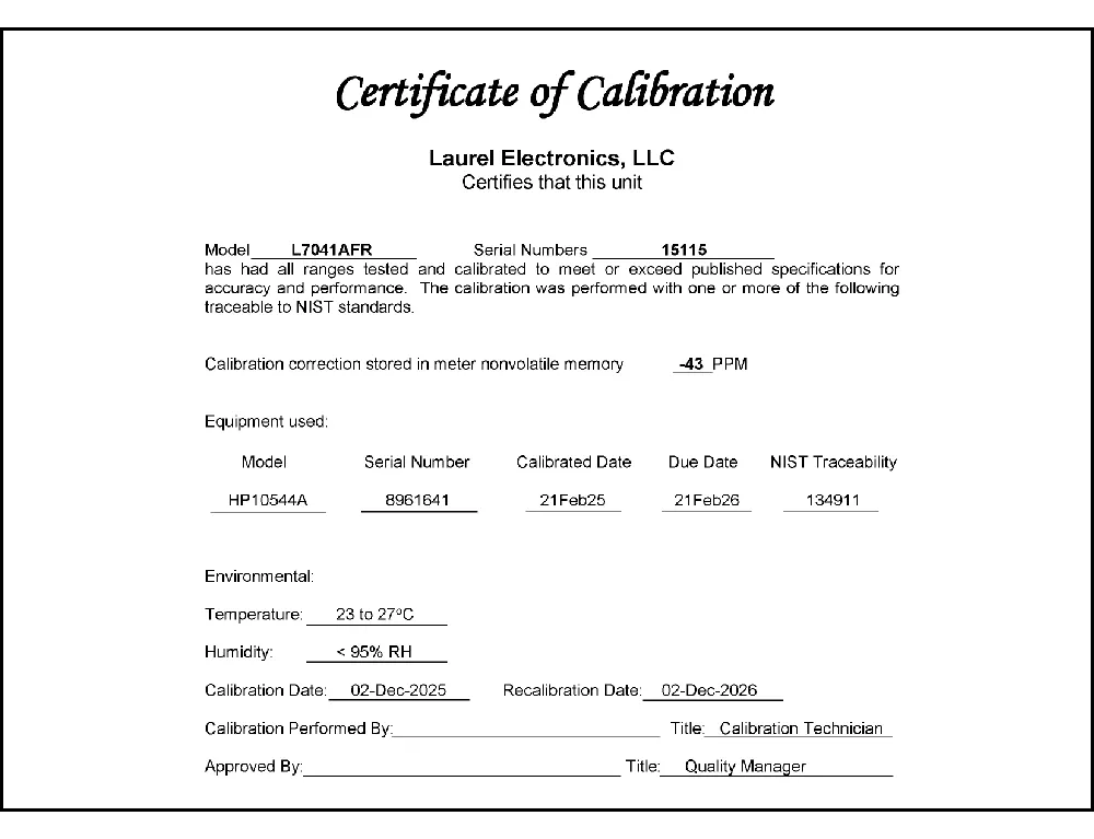
Certificate of Calibration
$65.00DLS-XLOG2
XLog2 Data logging Software
$495.00CON01
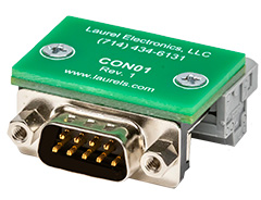
CON01 Connector
$75.00CBL6
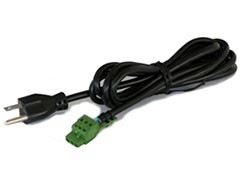
6-foot Power Cable
$41.00CBL12
12-foot Power Cable
$47.00CBL02
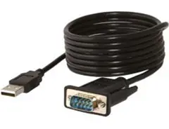
USB-to-RS232 Adapter Cable
$47.00CBL04
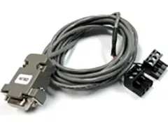
RS232 Cable for LT Transmitters
$47.00The Laureate™ LT Series DIN rail transmitter for batch controller analog input is a low cost, powerful, and highly accurate batching controller for repetitive fill operations, using the Laureate V-to-F analog signal conditioner for 4-20 mA, 0-1 mA, or 0-10V conditioned flow meter signals. Fill operations repeat continually with a programmable delay from 10 ms to 199.99 sec, or based on an external control input.
Three items are tracked by the batch control software, each scalable to engineering units and displayed on the controller's six-digit LED display. Item #1 is the current batch total, settable to count up from zero to a preset limit, or down from a preset limit to zero. Item #2 can be assigned to grand total or number of batches. Item #3 is the flow rate.
The Laureate VF voltage-to-frequency converter signal conditioner board converts 4-20 mA, 0-1 mA, or 0-10V conditioned flow meter signals to a frequency from 10 kHz to 110 kHz, allowing the controller to totalize flow, count up to a preset value, or count down to zero from a preset value for batch control. One relay is dedicated to On/Off batch control, while the second relay is available to slow down rate near the setpoint, or to provide another alarm or control function based on rate or total.
Relay control is provided by two or four 8A contact relays, or two or four 120 mA AC/DC solid state relays. Relay latching modes are latching or non-latching; active modes are active on or off, active high or low. Hysteresis modes include QA passband mode, split hysteresis, and span hysteresis.
The Extended Laureate computer board can display rate based on successive readings and allows exceptionally accurate custom curve linearization — for example, reading out liquid volume or flow rate in a horizontal cylindrical tank based on level reported by a 4-20 mA transmitter. Up to 180 data points are entered into a spreadsheet or text file; the computer calculates spline-fit segments, downloaded into the transmitter.
All signal conditioner board ranges are factory-calibrated, with calibration factors stored in EEPROM, enabling field replacement of signal conditioner boards without necessitating recalibration of the transmitter. Factory recalibration is recommended annually.
Documented description specifically frames the first relay as fixed to On/Off batch control (starting and stopping the actual fill), while the second is documented as available for a genuinely different purpose — slowing the rate near the setpoint, or serving another alarm/control function; this reflects that on/off batch control and setpoint-approach rate reduction are two documented, functionally distinct control actions, so dedicating one relay to each allows both to operate independently and simultaneously.
Documented description specifically frames this relay as being "available" for that purpose without detailing the specific external hardware required — since slowing rate near a setpoint inherently requires the process itself (a valve, pump, or feeder) to actually support a reduced flow state when commanded, the transmitter's documented role is providing the timely control signal, while the physical two-speed capability itself is documented as residing in the external fill equipment the relay is wired to.
Documented specification lists this specific frequency range for the V-to-F converter without further detail on the underlying design rationale — this range is consistent with the same inverse-period timing technique used throughout the LT Series, where a higher converted frequency generally supports faster, more responsive update rates for a given gate time, which is documented elsewhere as beneficial for batch control's need for fast alarm and control response.
Documented signal input options for this specific transmitter variant are limited to VF1 (4-20 mA), VF2 (0-1 mA), and VF3 (0-10V) — a genuinely different, separate LT Series batch controller variant is documented as using the FR pulse signal conditioner for direct turbine flow meter pulse input; this analog-input version is documented as specifically requiring an already-conditioned analog flow signal rather than accepting a raw turbine meter pulse train.
Documented description specifically states fill operations are "repeated continually with a programmable delay... or based on an external control input," presenting these as two separate triggering approaches — in the continually-repeating mode, the documented delay is consistent with counting from batch completion before the next cycle automatically begins, while the external-control-input mode is documented as a separate, alternative triggering method not governed by the same fixed delay timer.
The documented ordering structure lists VF1, VF2, and VF3 as separate signal input board selections at time of order, rather than describing them as software-only configuration options on one shared board — this is consistent with the specific V-to-F signal conditioner board itself being matched to the intended analog input type at the hardware level, distinct from other LT Series transmitters where a single board is documented as user-configurable across multiple signal types.
Documented specification lists these adjustment ranges once under the general digital span/zero adjustment specification, without separately restricting them per tracked item — since Item #1, #2, and #3 are each documented as independently scalable to engineering units, the same underlying ±999,999 adjustment capability is consistent with applying to whichever of the three items is being configured at a given time.
No — documented description presents these as alternative uses for the same single relay ("available to slow down rate near the setpoint, or to provide another alarm or control function"), meaning a given transmitter configuration assigns that second relay to one of these two documented roles at a time, not both simultaneously; a second physical relay (via the quad relay option) would be needed to implement both functions concurrently.
Documented specification describes the batch average filter as averaging each 16 conversions for this update rate, framed as a general signal-conditioning behavior rather than one specific to a single tracked item — since Items #1 through #3 are all derived from the same underlying conditioned signal, this filter setting is consistent with affecting the update behavior of all three tracked items together, not selectively applying to only one.
Documented specification lists the excitation output as standard, intended to power transducers or two-wire transmitters supplying the 4-20 mA/0-1 mA/0-10V signal into the VF converter — this excitation output is documented as a separate, supporting function for powering the external flow-conditioning transducer that produces the analog input, rather than being part of the transmitter's own internal V-to-F conversion or totalizing circuitry.
Documented terminology specifically defines fast fill as the initial, relatively high-rate filling stage used to introduce material into a container quickly, while dribble fill is the documented term for the subsequent slower fill rate used for the final portion — the switchover from fast to dribble fill, and the eventual termination of dribble fill, are documented as governed by feedback signals (typically from a scale or level sensor) rather than a fixed time or volume alone.
Documented explanation specifically identifies valve reaction time and hydraulic shock (water hammer) as the underlying problem a fast-only shutoff would face — material continues to flow briefly after a valve command to close, and this documented "coast" effect is proportionally larger at high flow rates; slowing to a documented dribble rate before final cutoff reduces the amount of material delivered during that reaction-time coast, improving final accuracy.
Yes — one documented industry guideline specifically describes the fast fill (coarse) stage delivering roughly 80-90% of total batch volume quickly, with the remaining portion delivered during the slower dribble stage; this documented split reflects the goal of using dribble fill only for the final accuracy-critical portion, not the majority of the batch, to keep overall cycle time reasonably short.
Documented field analysis specifically states that inaccuracies with flow-meter-based batch processes are generally concentrated at the beginning and end of the batch — this is broadly consistent with why two-speed fill control specifically targets the end-of-batch portion with a slower, more controllable dribble rate, since that documented error-prone region benefits the most from finer control.
Yes — documented guidance specifically warns that flow meter accuracy must remain consistent across a demanding turndown ratio (the ratio between the fast-fill flow rate and the much lower dribble-fill flow rate), and specifically flags that some flow meter technologies derate (lose accuracy) at very low flow rates; verifying a specific meter's accuracy at the actual dribble-fill flow rate, not just its nameplate full-scale accuracy, is documented as a genuine specification check.
Yes — documented guidance specifically recommends pneumatically actuated or two-stage solenoid valves over simple gate valves specifically because of their faster, more predictable response time when switching stages; this documented recommendation reflects that a slow or inconsistent valve response undermines the precision the two-speed fill strategy is intended to provide, regardless of how accurately the flow signal itself is being measured.
Documented industry analysis specifically flags this as a common misunderstood terminology issue — discrete two-stage (fast/dribble) valve control is fundamentally simple on-off logic with staged setpoints, which documented analysis distinguishes from genuine continuous PID control; describing a staged on-off batching approach as "PID" is documented as a frequent but technically inaccurate mischaracterization of the actual control algorithm being used.
Yes — documented guidance specifically describes integrating a load cell with a feeder to enable automatic correction: when the actual feeding rate deviates from the target, the system can adjust motor speed to bring output back toward the target, functioning as a documented closed-loop correction distinct from simply relying on an open-loop flow meter reading alone.