
Features
- Factory calibrated for thermocouple types J, K, T, E, N, R, S
- Accuracy ±0.01% of full span ± conformity error
- Entire range of each thermocouple in one scale
- User selectable input span from entire thermocouple range down to 15.0°
- Selectable 1° or 0.°1, degrees Celsius, Fahrenheit, Kelvin or Rankin
- All input ranges are user selectable and factory calibrated
- Up to 60 conversions per second, Ideal for peak or valley capture
- 4-20 mA, 0-20 mA, 0-10V or -10V to +10V transmitter output, (isolated)
- Analog output resolution 0.0015% of span, accuracy ±0.02% of span
- RS232 or RS485 serial data, Modbus or Laurel ASCII protocol (isolated)
- Dual 120 mA solid state relays for alarm or control (isolated)
- Power 85-264 Vac / 90-300 Vdc or 10-48 Vdc / 12-32 Vac (isolated)
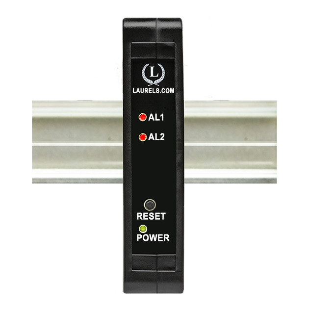
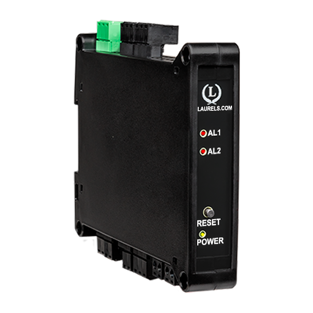
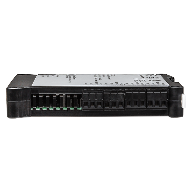
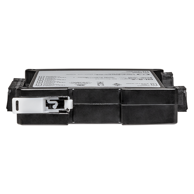
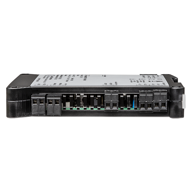
- DIN rail mount housing, 22.5 mm wide, detachable screw-clamp connectors
- Operating temperature from -40°C to 70°C (-40°F to 158°F)
Certificates of Compliance


The Laureate 4-20 mA, 0-20 mA, 0-10V or -10V to +10V and RS232/RS485 output transmitter for thermocouple input signal offers the same high performance, signal conditioning, and programmable features as Laureate digital panel meters, counters, and timers. It provides six voltage input ranges and four current input ranges, all factory calibrated and jumper selectable. This thermocouple transmitter delivers a linearized, highly accurate, stable, and repeatable output for thermocouple types J, K, T, E, N, R, or S. The thermocouple type and temperature range, specified in °C or °F, are user-selectable. The temperature range can be as wide as the entire span of the thermocouple type, or as narrow as 150 counts (such as 15.0°), limited only by considerations of electrical noise and digital filtering time constants.
All ranges for all thermocouple types are factory-calibrated, with calibration factors stored in EEPROM on the signal conditioner board. This allows temperatures sensors and signal conditioner boards to be changed in the field without recalibrating the transmitter. Factory recalibration is recommended every 12 months. For cold junction compensation (CJC), an external transistor is mounted adjacent to the thermocouple input to measure ambient temperature. That transistor is calibrated as a system with the signal conditioner board. All Laurel Electronics instruments undergo factory calibration using the industry-leading Fluke calibrators, which are recalibrated yearly and certified traceable to national standards, ensuring the highest level of precision and reliability.
Laureate Transmitters are easily programmed with Laurel’s free Instrument Setup Software, downloadable from our website and compatible with Windows PCs, requiring a data interface board for setup.
High read rate of up to 50 or 60 conversions per second, the Laureate™ LT Series transmitter uses Concurrent Slope (US Pat. 5,262,780) analog-to-digital conversion to integrate signals over a full power line cycle (50 Hz or 60 Hz). This read rate enables peak and valley capture, real-time computer interfacing, and control applications. Peak and valley values are automatically captured and can be viewed using Laurel’s free Instrument Setup Software (compatible with Windows PCs) or transmitted as serial data.Standard Features of Laureate LT Transmitters Include:
- Serial communications output, (isolated), RS232 or RS485 (half or full duplex), jumper selectable. Three protocols are user selectable: Modbus RTU, Modbus ASCII, or Laurel ASCII. Modbus operation is fully compliant with Modbus Over Serial Line Specification V1.0 (2002). The Laurel ASCII protocol is simpler than the Modbus protocol and is recommended when all devices are Laureates.
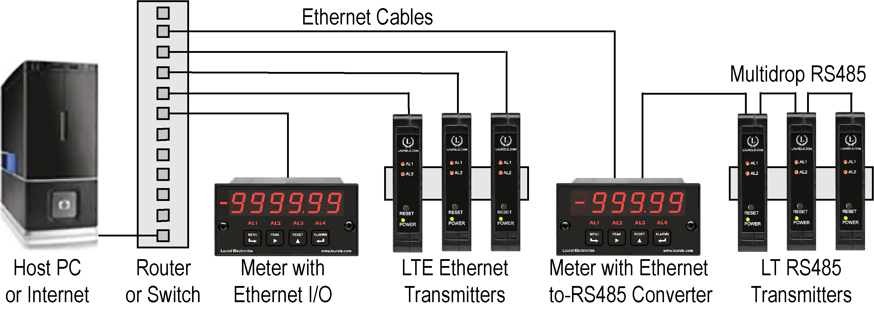
- 4-20 mA, 0-10V or -10V to +10V analog transmitter output, (isolated), jumper-selectable and user scalable. All selections provide 0.0015% resolution of output span and 0.02% output accuracy of a reading from -99,999 to +99,999 counts that is also transmitted digitally. Output isolation from signal and power grounds eliminates potential ground loop problems. Note that Ethernet data I/O is provided by Laurel's LTE series transmitters.
- Dual solid state relays, (isolated), for alarm or control. Rated 120 mA at 130 Vac or 170 Vdc.
- Selectable transducer excitation output, (isolated), user selectable 5V@100 mA, 10V@120 mA, 12V@100 mA, or 24V@50 mA.
- Power 85-264 Vac, (isolated), low-voltage 10-48 Vdc or 12-32 Vac power is optional.
Digital signal filtering modes can be selected to ensure stable readings in electrically noisy environments.
- An unfiltered selection provides true peak and valley readings and aids in control applications.
- A batch average filter selection averages each 16 conversions.
- An adaptive moving average filter selection provides a choice of 8 time constants from 80 ms to 9.6 seconds. When a significant change in signal level occurs, the filter adapts by briefly switching to the shortest time to follow the change, then reverts back to its selected time constant. An Auto setting selects the time constant selection based on signal noise.
Two tare functions: auto-tare and manual tare. In auto-tare, an input line is grounded by an external pushbutton. This causes the current weight, which is normally the empty weight of the container to be stored in memory as an offset. In manual tare, the tare value can be entered manually via a control input pushbutton or using Laurel's free Instrument Setup Software.
Peak and valley values are automatically captured. These may be displayed via Laurel's free Instrument Setup Software, which runs on a PC under MS Windows or can be transmitted as serial data.
Two control inputs (CMOS/TTL levels, logic 0 = tied to digital ground, logic 1 = open) or dry contacts that can be set to control / activate 14 transmitter commands.

LT series DIN rail Transmitters & signal conditioners can be interfaced to a wide range of sensors and transducers using one of seven available plug-in signal conditioner boards. The transmitters duplicate the high performance (high accuracy, high read rate) and extensive programmable features of Laureate 1/8 DIN digital panel meters, counters and timers. They utilize the same signal conditioners boards, much of the same firmware, and Laurel's free Windows-based Instrument Setup Software. They come in a compact DIN rail mount package with detachable screw-clamp connectors for easy wiring.
The LT series Transmitters accessible from this page include a 4-20 mA, 0-20 mA, 0-10V, or -10V to +10V analog output (isolated, user selectable), an RS232 or RS485 serial data interface (isolated, user selectable), and dual 120 mA solid state AC/DC relays (isolated). An (isolated) 5, 10, 12, or 24 Vdc transducer excitation output is included with all models other than those with a temperature or AC RMS signal conditioner.
Connecting Laureate LT Transmitters to a Local Area Network (LAN)
Up to 30 Laureate LT Transmitters and/or Digital Panel Meters can be configured for RS485 and daisy-chained to an LT Transmitter for seamless LAN integration. Alternatively, Laurel LTE series Ethernet transmitters can connect directly to a LAN via an Ethernet cable. Setup for both configurations is streamlined using Laurel’s free Instrument Setup Software, which simplifies node discovery and transmitter configuration.
Flexible Communication Options for LT Transmitters
Laureate Transmitters can be equipped with Laurel communication boards to support various interfaces and protocols. These include serial interfaces with ASCII or Modbus RTU protocols, and Ethernet interfaces with web access, ASCII, or Modbus TCP/IP protocols, ensuring versatile connectivity for your commercial applications.
| LT Transmitter Signal Input & Function | Model Series | Analog Output | RS232 & RS485 | Dual Relays | |
|---|---|---|---|---|---|
| 1 | DC Input Voltage and Current | LT-DC |  |
|
|
| 2 | AC RMS Voltage or Current | LT-RMS | |
|
|
| 3 | Process Voltage or Current | LT-P | |
|
|
| 4 | Weighing Applications | LT-WA | |
|
|
| 5 | Load Cell & Microvolt Signals | LT-WM | |
|
|
| 6 | Thermocouple (Types J, K, T, E, N, R, S) | LT-TC | |
|
|
| 7 | RTD Temperature | LT-RTD | |
|
|
| 8 | Resistance in Ohms | LT-R | |
|
|
| 9 | Frequency, Rate, Speed | LT-FR | |
|
|
| 10 | Pulse Input Totalizer | LT-FR | |
|
|
| 11 | Process Signal Totalizer | LT-VF | |
|
|
| 12 | Sum, Difference, Ratio, Product of 2 Inputs | LT-FR | |
|
|
| 13 | Batch Controller Pulse Input | LT-FR | |
|
|
| 14 | Batch Controller Analog Input | LT-FR | |
|
|
| 15 | On/Off Duty Cycle | LT-FR | |
|
|
| 16 | Stopwatch Timing for Single Events | LT-FR | |
|
|
| 17 | Average Time of Periodic Events | LT-FR | |
|
|
| 18 | AC Phase Angle and Power Factor | LT-FR | |
|
|
| 19 | Quadrature Position or Rate | LT-QD | |
|
|
Thermocouple input signal transmitter
| TC Types | Range | Conformity Error |
|---|---|---|
| J | -210°C to +760°C (-347°F to +1400°F) | ±0.09°C (±0.16°F) |
| K | -244°C to +1372°C (-408°F to +2501°F) | ±0.1°C (±0.17°F) |
| T | 0°C to +400°C (32°F to 752°F) -257°C to 0°C (-430°F to +32°F) |
±0.03°C (±0.05°F) ±0.2°C (±0.36°F) |
| E | -240°C to +1000°C (-400°F to +1830°F) | ±0.18°C (±0.32°F) |
| N | -245°C to +1300°C (-410°F to +2370°F) | ±0.10°C (±0.17°F) |
| R | -45°C to +1768°C (-49°F to +3214°F) | ±0.17°C (±0.31°F) |
| S | -46°C to +1768°C (-51°F to +3213°F) | ±0.12°C (±0.22°F) |
| Recalibration: All ranges are calibrated at the factory. Recalibration is recommended every 12 months. | ||
| Analog Input | ||||
|---|---|---|---|---|
| Calibration | NIST Monograph 125 (IPTS-68) | |||
| Input Resistance | 1 GΩ | |||
| Input Current | 100 pA | |||
| Max Lead Resistance | 1 kΩ max for rated accuracy | |||
| Overall Error at 25°C | ±0.01 of full scale ±2 counts | |||
| Span Tempco | ±0.003% of reading/°C | |||
| Ref Junction Tempco | ±0.02 deg/deg | |||
| Overvoltage Protection | 125 Vac | |||
| NMR at 50/60 Hz | 80 dB plus selectable filter from 80 ms to 9.6 s time constant | |||
| CMR, DC-60 Hz | 120 dB with 500Ω imbalance | |||
| CMV, DC-60 Hz | 250 Vac from power and earth grounds | |||
| Open Sensor Indication | 0 mA or > 20 mA output, selectable | |||
| Analog Output (standard) | ||||
| Output Levels | 4-20 mA, 0-20 mA, 0-10 Vdc, -10 to +10Vdc (user selectable) | |||
| Compliance at 20 mA | 10V (0-500Ω load) | |||
| Compliance at 10V | 2 mA (5 kΩ or higher load) | |||
| Output Resolution | 16 bits (65,536 steps) | |||
| Output Error | ±0.02% of output span ± overall input error | |||
| Output Isolation | 250V rms working, 2.3 kV rms per 1 minute test | |||
| Step Response Time | 50 ms | |||
| Serial Data Output (standard) | ||||
| Signal Types | RS232 or RS485 (half or full duplex), jumper selectable | |||
| Data Rates | 300, 600, 1200, 2400, 4800, 9600, 19200 baud | |||
| Output Isolation | 250V rms working, 2.3 kV rms per 1 min test | |||
| Serial Protocols | Modbus RTU, Modbus ASCII, Custom ASCII | |||
| Modbus Compliance | Modbus over Serial Line Specification V1.0 (2002) | |||
| RS232/485 Connector | Screw terminals for easy daisy chaining | |||
| Digital Addresses | 247 for Modbus, 31 for Custom ASCII | |||
| Dual Relay Output (standard) | ||||
| Relay Type | Two solid state relays, SPST, normally open, Form A | |||
| Load Rating | 120 mA at 140 Vac or 180 Vdc | |||
| Power Input | ||||
| Standard Power | 85-264 Vac or 90-300 Vdc | |||
| Low Power Option | 10-48 Vdc or 12-32 Vac | |||
| Power Frequency | DC or 47-63 Hz | |||
| Power Isolation | 250V rms working, 2.3 kV rms per 1 min test | |||
| Power Consumption at 24V | 1.5W typical | |||
 |
||||
| Environmental | ||||
| Operating Temperature | -40°C to 70°C (-40°F to 158°F) | |||
| Storage Temperature | -40°C to 85°C (-40°F to 185°F) | |||
| Relative Humidity | 95% at 40°C, non-condensing | |||
| Cooling Required | Mount transmitters with ventilation holes at top and bottom. Leave 6 mm (1/4") between transmitters, or force air with a fan. | |||
| Mechanical | ||||
| Enclosure | Rugged black polycarbonate housing material | |||
| Mounting | 35 mm rail per DIN EN 50022 | |||
| Dimensions | 129 x 104 x 22.5 mm case | |||
| Connectors | Detachable screw clamp connectors meet VDE / IEC / UL / CSA standards. RJ45 jack for Ethernet | |||
| Tightening Torque | Screw terminal connectors: 5 lb-in (0.56 Nm) | |||
| Weight | Complete transmitter: 183 g (6.5 oz) | |||
| Replacement Case Screws | ||||
| Size | 6 | |||
| Thread Pitch | 6-19 | |||
| Length | 1/2" | |||
| Head Style | Pan Head | |||
| Drive Style | Phillips | |||
| Head Diameter | 0.256-0.270 | |||
| Head Height | 0.087-0.097 | |||
| Full/Partial Thread | Full | |||
| Drive Size | 2 | |||
| Material | Steel | |||
| Finished | Black Oxide | |||
| General | ||||
| Programming | Utilize Laurel's free Instrument Setup Software, which runs on a PC under MS Windows. | |||
| Security | Lockout options available using Laurel's free Instrument Setup Software. | |||
| Warranty | 3 years parts & labor | Recalibration: All ranges are calibrated at the factory. Recalibration is recommended every 12 months. | ||
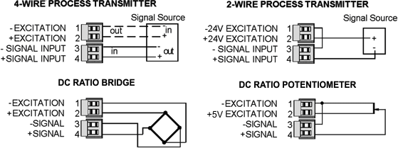
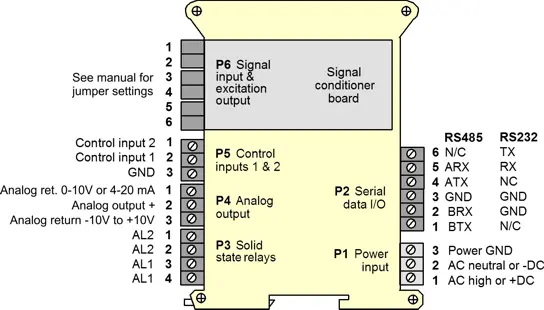
Transmitter Pinout
Operation as a Fast ON/OFF Controller or Supervisory Monitor
 With the optional dual solid state relay output option, which has a typical response time of only 17 ms, Laureate temperature meters and transmitters can serve as extremely fast and accurate ON/OFF controllers for closed-loop temperature control. They can also serve as supervisory process monitors and provide alarms or shutoffs when processes exceed normal limits.
Multiple setpoint operating modes are individually selectable for each relay, as explained in the dual-setpoint controller page. Relay duty cycles and chatter can be minimized with programmable hysteresis and time delays. A band deviation operating mode can be selected for each relay, where an alarm is generated whenever the reading is a selected number of counts above or below the setpoint. The relay modes have to be non-latching, since 4-20 mA temperature transmitters do not offer external reset.
Free Instrument Setup Software for Series 2 Laureates
|
|
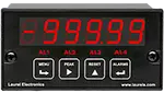
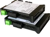
| 1/8 DIN Digital Panel Meters | DIN Rail Transmitters |
Free Downloadable Windows-based Instrument Setup (IS) software (Data Interface Board Required) for use with our programmable Digital Panel Meters, Scale Meters, Counters, Timers, Remote Displays, and Transmitters, are an easy method to set up Laureate 1/8 DIN digital panel meters, counters, timers, remote displays, and DIN-rail transmitters, as explained in the Instrument Setup Software Manual. Laureate 1/8 DIN instruments can also be set up from the front panel, as explained in their respective Owners Manuals. Instrument Setup software is of benefit whether or not the PC is connected to the instrument.
- When the PC is connected to the instrument, Instrument Setup software can retrieve the setup file from the instrument or open a default setup file or previously saved setup file from disk View Setup, then provides graphical user interface (GUI) screens with pull-down menus applicable to input, display, scaling, filtering, alarms, communications, analog output, and front panel lockouts. Fields that are not applicable to the instrument as configured are either left out or grayed out. Clicking on any item will bring up a detailed Help screen for that item. After editing, the setup file can be downloaded, uploaded to the instrument, or saved to a disk. The same setup file can then be downloaded into multiple instruments.
- When the PC is not connected to the instrument, the above GUI screens can be used to set up a virtual instrument. The setup file can then be saved to disk. Switching toView Menu then brings up a screen with the required front panel programming steps. This view can be printed out for use at the instrument site and to serve as a hard copy record.
Download Free Instrument Setup Software
Installation
Set User Account Control (UAC) of MS Windows to "Never notifiy me" so that Instrument Setup Software can create directories. The UAC change screen can be reached as follows:
- Under Windows 7, click on the Windows Start button in the lower left of the desktop and enter "UAC" in the search field.
- Under Windows 8, navigate to Control Panel, then to the "User Accounts and Family Safety" section, and click on "Change User Account Control Settings."
- Under Windows 10, click on the Windows Start button in the lower left of the desktop, then on "Settings", and enter "UAC" in the search field.
- Reboot your computer for the changed UAC setting to take effect.
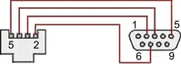
RJ11-to-DB9 cable with rear view of DB9 connector to PC
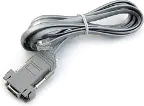
RS232 cable, meter to PC, P/N CBL01
Laureate 1/8 DIN Laureate instruments must be equipped with a serial communications board and be connected to the computer via a serial communications cable. The connection can be via RS232, RS485, USB or Ethernet. Following setup, the serial communications board may be removed from the instrument if desired. The wiring of the RS232 cable is illustrated above with end views of the two connectors.
Laureate LT Series transmitters come standard with a 3-wire serial interface, which can be jumpered for RS232 or RS485.
Laureate LTE Series transmitters come standard with an Ethernet interface.
Meter Setup Screens
Click on any of the reduced screens below for a full-size screen view, then click on the Back button of your browser to return to this page. The screens examples below are for a fully-loaded Series 2 Digital Panel Meter (DPM), which is connected to the PC via RS232. If the meter is a Series 1 meter (pre-2007), this is sensed by the software, and somewhat different screens are brought up. Please see Series 1 setup screens.

Welcome Screen
From the computer desktop, click on Start > Programs > IS2 > IS2. Or click on the IS icon on your desktop. This splash screen will be displayed for three seconds. The software revision number is in the lower right.


Communications Selection Screen
Specify your desired communication protocol and the serial communications bus type, which should match the jumper setup of the instrument. Select None if the PC is not connected to the instrument.

Establish Communications Screen
If you selected RS-232, you will be asked to specify the PC Com Port and Baud Rate, which should match the jumper setup of the instrument. Click on Establish. With the right settings, the Communications Established field will light up in green, and the Meter Type will be recognized. If so, click onMain Menu.

Main Menu Screen
Click on File > Default Setup to retrieve the default setup file from disk for your type of meter. Click on File > Open Setupto retrieve a previously saved setup file from disk or on File > Save Setup to save your edited setup file to disk. Click onDPM > Get Setup to retrieve the setup file from your meter or on DPM > Put Setup to download your edited setup file into the meter.

DPM Input + Display Setup Screen
From the Main Menu, click on View > Setup, then on theInput+Display tab. You can now specify the meter hardware, signal type, display mode, and functions of control inputs A and B. Clicking on any item brings up a pull-down menu with the available choices.

DPM Scaling Setup Screen
Click on the Scaling tab, which provides three scaling methods to relate the signal to the displayed reading: 1) Scale and Offset method, 2) Coordinates of two points method, and 3) Reading Coordinates of Two Points method. The last method uses actual high and low signals, and the computer will prompt you.

DPM Filter Setup Screen
Click on the Filter tab, which allows you to specify the digital filter time constant (if any), the adaptive filter threshold, and whether Peak / Valley values are filtered or unfiltered. As for all setup screens, clicking on the F1 key while an item is highlighted brings up a Help screen for that item, as illustrated.

DPM Relay Alarms Setup Screen
Click on the Relay Alarms tab, which allows you to set up Alarms 1 and 2 for the optional dual relay output board. Clicking on any of the four numeric fields changes these to green and brings up a special field to enter the desired numeric value, which is tied to the displayed reading.

DPM Communications Setup Screen
Click on the Communications tab so set up serial communications. In particular, you can special the Serial Protocol and the meter address if multiple meters are to be addressed on the same serial data line.

DPM Analog Output Setup Screen
Click on the Analog Out tab so set up the optional analog output board. Three output ranges are selectable, the endpoints of which can be tied to user-specified High and Low readings.

DPM Lockouts Setup Screen
Click on the Lockouts tab to check off menu items which will no longer be accessible from the front panel of the meter. This will simplify meter operation and prevent unintended setup changes.
Meter Setup Utilities

DPM Front Panel Setup Screen
As an aid to programming the meter from the front panel when a serial connection is not available, you can return to the Main Menu and click on View > Menu. The required sequence of front panel screens will then be displayed. Click on any step in the sequence for the meaning of each digit, as illustrated for the FILtEr step. For a hardcopy, simply press on Print.

DPM Jumper Setup Screen
Specify your desired communication protocol and the serial communications bus type, which should match the jumper setup of the instrument. Select None if the PC is not connected to the instrument.

DPM Jumper Setup Screens
Click on any of the displayed plug-in boards, and you will be presented with the jumper positions and electrical connections for your selected board. This minimizes the need to refer to the printed manual.

DPM Commands Screen
This page allows you set up external input, serial communications, an analog output proportional to the display (optional), and lockouts for Laureate digital counters. The grayed out area at the top right of the screen applies to Laureate remote displays.


Graphical Output Screens (not available with Ethernet)
From the Main Menu, click on Readings if your PC is connected to the meter. A pull-down menu then offers three choices: List, Plot and Graph.
- List presents the latest readings in a 20-row by 10-column table. Press Pause at any time to freeze the display. This is one method to capture peak readings.
- Plot generates a plot of readings vs. time in seconds. It effectively turns the DPM-PC combination into a printing digital oscilloscope.
- Graph generates a histogram where the horizontal axis is the reading and the vertical axis is the number of occurrences of readings. The display continually resizes itself as the number of readings increases.

DPM Calibration Screens
Click on the Scaling tab, which provides three scalClick on the Scaling tab, which provides three scaling methods to relate the signal to the displayed reading: 1) Scale and Offset method, 2) Coordinates of two points method, and 3) Reading Coordinates of Two Points method. The last method uses actual high and low signals, and the computer will prompt you.

Frequency Meter Calibration Screen
Calibration of the quartz crystal of the Laureate frequency meter requires the input of a known frequency from a calibrator. Apply the frequency, then enter the frequency in Hertz. Calibration will be automatic, with storage of the calibration factor stored in non-volatile memory.
Dimensions
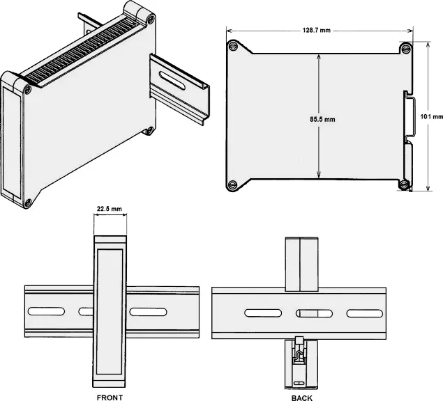
Dimensioned CAD assembly drawings in EPRT, STEP, x_t, .dwg, pdf file formats: Laureate-transmitter-case.zip (zipping prevents browser from opening CAD files as text files).


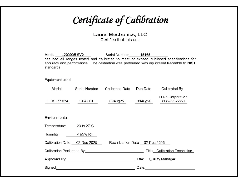
CAL-Analog
Certificate of Calibration
$65.00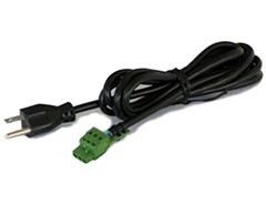

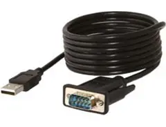
CBL02
USB-to-RS232 Adapter Cable
$47.00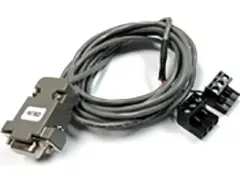
CBL04
RS232 Cable for LT Transmitters
$47.00CBL12
12-foot Power Cable
$47.00CBL6
6-foot Power Cable
$41.00Understanding the Laureate™ LT Series DIN Rail Transmitter for Thermocouple Temperature
The Laureate™ LT Series DIN rail transmitter for thermocouple input delivers a linearized, highly accurate, stable, and repeatable output for thermocouple types J, K, T, E, N, R, or S. The thermocouple type and temperature range, specified in °C or °F, are user-selectable. The temperature range can be as wide as the entire span of the thermocouple type, or as narrow as 150 counts (such as 15.0°), limited only by considerations of electrical noise and digital filtering time constants.
Per-Type Conformity Error
Each thermocouple type carries its own documented conformity error over its full range: Type J is ±0.09°C (±0.16°F) over -210°C to +760°C; Type K is ±0.1°C (±0.17°F) over -244°C to +1372°C; Type T is ±0.03°C (±0.05°F) from 0°C to +400°C and ±0.2°C (±0.36°F) from -257°C to 0°C; Type E is ±0.18°C (±0.32°F) over -240°C to +1000°C; Type N is ±0.10°C (±0.17°F) over -245°C to +1300°C; Type R is ±0.17°C (±0.31°F) over -45°C to +1768°C; and Type S is ±0.12°C (±0.22°F) over -46°C to +1768°C.
Input Signal Specifications
Calibration is per NIST Monograph 125 (IPTS-68). Input resistance is 1 GΩ, with input current of 100 pA. Maximum lead resistance for rated accuracy is 1 kΩ. Overall error at 25°C is ±0.01% of full scale ±2 counts. Span tempco is ±0.003% of reading/°C; reference junction tempco is ±0.02 deg/deg. Overvoltage protection is 125 Vac. NMR at 50/60 Hz is 80 dB plus a selectable filter with time constant from 80 ms to 9.6 s. CMR (DC-60 Hz) is 120 dB with 500Ω imbalance; CMV (DC-60 Hz) is 250 Vac from power and earth grounds.
Cold Junction Compensation and Open Sensor Indication
For cold junction compensation (CJC), an external transistor mounted adjacent to the thermocouple input measures ambient temperature; that transistor is calibrated as a system with the signal conditioner board. Open sensor indication is selectable as 0 mA or greater than 20 mA output.
Fast ON/OFF Control & Supervisory Monitoring
With the optional dual solid state relay output, which has a typical response time of only 17 ms, Laureate temperature transmitters can serve as extremely fast and accurate ON/OFF controllers for closed-loop temperature control, or as supervisory process monitors providing alarms or shutoffs when processes exceed normal limits. Multiple setpoint operating modes are individually selectable for each relay; relay duty cycles and chatter can be minimized with programmable hysteresis and time delays. A band deviation mode can be selected for each relay, generating an alarm whenever the reading is a selected number of counts above or below the setpoint. Relay modes must be non-latching, since 4-20 mA temperature transmitters do not offer external reset.
Factory-Calibrated Accuracy
All ranges for all thermocouple types are factory-calibrated, with calibration factors stored in EEPROM on the signal conditioner board, allowing sensors and boards to be changed in the field without recalibrating the transmitter. The same signal conditioner board can be user-configured for all listed thermocouple types and °C or °F. Factory recalibration is recommended every 12 months.
Where Thermocouple Temperature DIN Rail Transmitters Are Used
- Furnace & Kiln Temperature Control — fast ON/OFF control with 17 ms relay response.
- Multi-Type Thermocouple Retrofit — a single transmitter field-configurable across seven thermocouple types.
- Process Supervisory Alarming — band deviation and hysteresis-based alarm configuration.
- 4-20 mA Temperature Retransmission — linearized thermocouple output for PLC/SCADA integration.
- Long-Lead-Length Installations — accuracy maintained up to 1 kΩ lead resistance.
- Multi-Point RS485 Temperature Networks — daisy-chained transmitters reporting to a central controller.
- OEM Temperature Instrumentation — DIN rail integration into existing control panels.
Thermocouple DIN Rail Transmitter Frequently Asked Questions
Why does Type T have two different documented conformity errors instead of one figure across its full range?
Documented specification specifically splits Type T's conformity error into two segments — ±0.03°C from 0°C to +400°C, and a wider ±0.2°C from -257°C to 0°C — reflecting that thermocouple conformity to its standard reference table isn't uniform across the full temperature span; the sub-zero portion of Type T's range is documented with a specifically wider error tolerance than its above-zero portion.
Does the 1 kΩ maximum lead resistance figure limit how far a thermocouple can physically be from the transmitter?
Indirectly, yes — documented specification ties rated accuracy specifically to lead resistance staying at or under 1 kΩ; since lead resistance increases with wire length and decreases with larger wire gauge, this figure functions as a practical constraint on the combination of distance and wire gauge used, rather than being expressed directly as a maximum distance figure itself.
Why is CJC performed with an external transistor mounted adjacent to the thermocouple input, rather than measuring temperature elsewhere in the transmitter?
Documented description specifically places this compensation transistor adjacent to the thermocouple input terminals — since cold junction compensation must correct for the actual temperature at the point where the thermocouple wire connects to the transmitter's copper terminals (the reference junction), the sensing element needs to be physically close to that specific junction rather than measuring an unrelated location inside the transmitter that might run at a different temperature.
Does selecting "0 mA" versus "greater than 20 mA" for open sensor indication change anything besides which direction the output goes on failure?
Not as documented — this is described as a simple selectable choice between two output states specifically triggered by an open sensor condition; the underlying detection of the open-sensor condition itself is documented as the same regardless of which of the two output responses (0 mA or above 20 mA) is selected to represent that failure state.
Why must relay modes be non-latching specifically because 4-20 mA temperature transmitters lack external reset?
Documented reasoning specifically connects these two facts: a latching relay, once tripped, would normally require an external reset input to clear it and resume normal operation — since this transmitter's documented interface doesn't provide that external reset capability, a latched relay would have no way to be cleared, which is why the documented relay modes are restricted to non-latching operation on this particular transmitter type.
Does the 17 ms relay response time apply to the transmitter's temperature reading itself, or only to the relay's physical switching action?
Documented description specifically frames the 17 ms figure as the "typical response time" of the dual solid state relay output option itself — this describes how quickly the relay switches once triggered, distinct from the transmitter's own signal conversion and measurement timing, which is governed separately by its documented Concurrent Slope™ conversion process.
Can the same physical transmitter be field-reconfigured from one thermocouple type to another, or does changing type require a different hardware model?
Documented note specifically states the same signal conditioner board can be user-configured for all listed thermocouple types and for °C or °F — this points to configuration-level flexibility on shared hardware rather than needing a separate physical transmitter model purchased for each individual thermocouple type.
Does the documented ±0.02 deg/deg reference junction tempco figure describe a large or small potential error source compared to the per-type conformity error?
It's a proportional figure rather than a fixed value, so its practical size depends on the ambient temperature swing at the transmitter's cold junction — a small ambient shift produces a correspondingly small reference-junction error, while a larger ambient swing scales that error up proportionally; this is documented as a separate error contributor from the fixed per-type conformity error, meaning the two figures address different sources of inaccuracy rather than one subsuming the other.
Does the selectable digital filter time constant (80 ms to 9.6 s) interact with the documented 80 dB NMR figure at 50/60 Hz?
Documented specification lists these together as complementary noise-rejection mechanisms — the 80 dB NMR figure describes a baseline rejection of 50/60 Hz normal-mode noise, while the separately selectable digital filter (with its own adjustable time constant) is documented as available in addition to that baseline figure, letting an installation add further smoothing for signals with noise beyond what the baseline NMR spec alone addresses.
Can the 125 Vac overvoltage protection rating be exceeded briefly without damaging the transmitter, or is it a hard limit?
The page documents 125 Vac specifically as the overvoltage protection rating for the thermocouple input, without further detail on transient or brief-excursion tolerance beyond that figure — treating it as the documented limit for the input protection circuitry, rather than assuming any specific margin above it, is the appropriate way to read this specification absent further documented detail.
Thermocouple Burnout & Open-Sensor Detection Questions From the Field
Why is an open (burned-out) thermocouple specifically problematic for high-input-impedance measuring instruments?
Documented explanation specifically identifies the core issue: with the circuit open, there's no complete path for the instrument's high-impedance input to reference against, which makes it susceptible to picking up electrical noise from nearby sources such as power lines, motors, and variable-frequency drives — that stray noise can then be falsely interpreted as a wildly varying, meaningless temperature reading rather than a clear failure indication.
What is the documented difference between "upscale" and "downscale" burnout protection modes?
Documented guidance specifically describes upscale burnout as forcing the output to a high, full-scale-like reading when the sensor fails open, while downscale burnout forces the output toward a low reading instead — the correct choice is documented as depending on the application's safety requirements, such as a heating process wanting an open sensor to read as dangerously hot (upscale) so the control system shuts the heat off, rather than misreading it as dangerously cold.
Why would a heating application specifically want burnout protection set to upscale rather than downscale?
Documented field example specifically explains that if a furnace's sensing thermocouple fails open without upscale burnout protection, the lost signal could be misread as a very low measured temperature — this would fool a controller into increasing heat input to compensate for what it thinks is a cold process, when the process may actually already be at or above a safe operating temperature, risking a dangerous upset; upscale burnout instead drives the reading high, causing the controller to shut the heat off.
Is a burned-out thermocouple the only documented cause of the same failure symptom a burnout mode is designed to catch?
No — documented guidance specifically notes that something as simple as a wire in the instrument loop becoming disconnected produces the identical effect as an actual thermocouple burnout, from the instrument's perspective; this is documented as a reason burnout protection is considered good practice for all thermocouple applications generally, not just ones where thermocouple failure itself is the primary concern.
Are there documented typical current values used to represent upscale versus downscale burnout on a 4-20 mA transmitter output?
Yes — documented industry reference specifically cites typical values of 3.2 mA or below for downscale burnout indication, and 21.6 mA or above for upscale burnout indication on a 4-20 mA transmitter loop — both figures documented as deliberately placed outside the normal 4-20 mA measurement range so the burnout condition is unambiguous to downstream equipment.
How does a basic thermocouple burnout detection circuit typically create a defined signal state when the sensor circuit opens?
Documented circuit description specifically explains that a resistor is placed to provide an alternate current path specifically for the open-circuit condition — this resistor is documented as sized in the mega-ohm range specifically to minimize its effect on the signal during normal operation when the thermocouple circuit is complete, while still providing a defined path that drives the output to a known state once the circuit opens.
Does burnout/open-sensor protection matter equally for RTD-based temperature transmitters, or is it specific to thermocouples?
Documented guidance specifically extends this concern to RTDs as well — one documented example describes an RTD failing open (resistance becoming very high), which without burnout protection could similarly be misread by the instrument, illustrating that the underlying burnout-function concept is a general good practice across different sensor technologies used with temperature transmitters, not a thermocouple-specific consideration alone.
Is periodically verifying that a burnout/open-sensor detection scheme is correctly configured considered good ongoing practice, or is it a one-time setup task?
Documented field guidance frames burnout mode selection as a configuration choice that should be deliberately verified for each specific application's safety requirements (heating versus cooling, for example) — one documented forum discussion specifically recommends confirming this setting is one of the first things checked when reviewing an existing installation, rather than assuming a default configuration is automatically appropriate for the application at hand.
